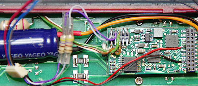
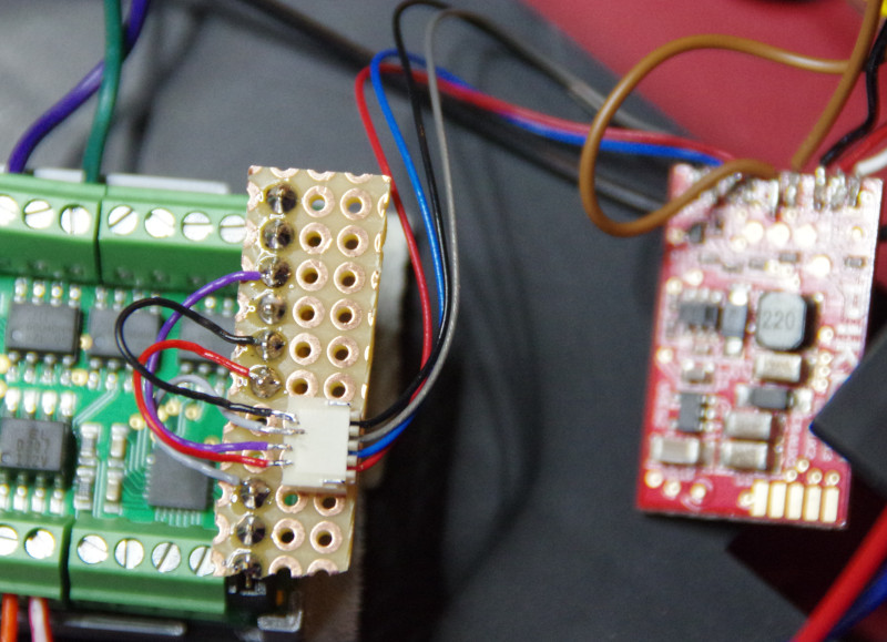
The SUSI interface allows the separation of decoder and sound module. In the meantime, there are tiny SUSI sound modules and even speakers with built-in SUSI sound modules. This means that even in tight spaces, the chances are good to enjoy locomotive sound with CTC.
The SUSI interface can currently be retrofitted to all CTC locomotive modules (except CTC locomotive module H0a). You only need the latest firmware (at least 20230902) and the CTC app version 4.19 or newer.
The SUSI module must handle 3.3 Volt signal levels and tolerate track voltage as its power supply. The support from Uhlenbrock has confirmed these data for the current IntelliSound 6 Modules.
Since our existing CTC locomotive modules do not have a SUSI socket, an appropriate adapter must be made for them. How this is done is documented below and in our locomotive conversions. If required, we will be happy to create a suitable adapter for you.
Original Sound
There are locomotives that use a SUSI module for sound by default. In this case, you can directly control the motor and locomotive functions with CTC and still enjoy the original sound of your locomotive. This works, for example, with PIKO’s G scale model of the BR50.
Retrofitting Sound
If you do not value the original sound or if the locomotive to be upgraded to CTC did not have any sound, you can purchase a SUSI sound module and connect it to the CTC locomotive module.
The Märklin BR247, which always accompanies us to our exhibitions, has now been equipped with SUSI sound. Details can be found in the BR247 conversion report.
SUSI Adapter for CTC Locomotive Modules
The four pins of the SUSI-classic socket must be connected as follows:
- Plus (red) to VBB
- Ground (black) to GND
- Data (grey) via a minimum of 470 Ohm resistor to a GPIO pin of the processor
- Clock (blue) via a minimum of 470 Ohm resistor to a GPIO pin of the processor
Adapter for CTC Locomotive Module 21mtc

For the CTC locomotive module 21mtc:
- Clock (blue) is connected to “Input-1 (Pin 33)” on the additional socket, and
- Data (grey) is connected to “Input-2 (Pin 32)” on the additional socket.
Additionally, we need to connect Plus (red) to VBB and Ground (black) to GND:
- In the picture, we did this directly at the solder pads of the 21mtc socket.
- Alternatively, the much larger solder pads intended for the support capacitor on the other side of the CTC locomotive module can be used.
Adapter for CTC Locomotive Module PluX22
For the CTC locomotive module PluX22:
- Clock (blue) is connected to “NFC TX (Pin 25)” on the additional socket, and
- Data (grey) is connected to “NFC RX (Pin 23)” on the additional socket.
Additionally, we need to connect Plus (red) to VBB and Ground (black) to GND:
- This can be done directly at the solder pads of the 21mtc socket, as with the 21mtc.
- Alternatively, the much larger solder pads intended for the support capacitor of the CTC locomotive module can be used.
Adapter for CTC Locomotive Module G

For the CTC locomotive module G, we use the servo connections:
- Clock (blue) is connected to “Servo-2 PWM”.
- Data (grey) is connected to “Servo-1 PWM”. Since the servo connections on the CTC module are already equipped with a 1 kOhm resistor, no separate resistor is needed here.
Via the socket intended for the 5 Volt voltage regulator, we can connect Plus (red) to VBB and Ground (black) to GND.


