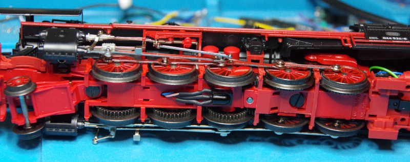
The locomotive is opened from below by the two screws next to the cylinders and the screw in front of the last drive axle. The tender is only clipped on:
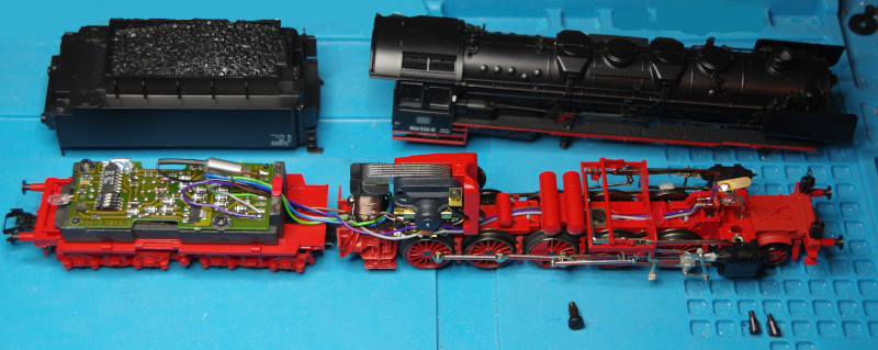
The locomotive presents itself as a Märklin locomotive with Delta electronics (Märklin No. 66415) in the tender.
The photos document the condition before I started desoldering wires:
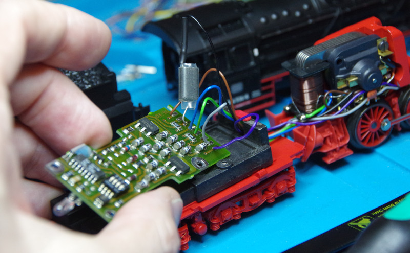
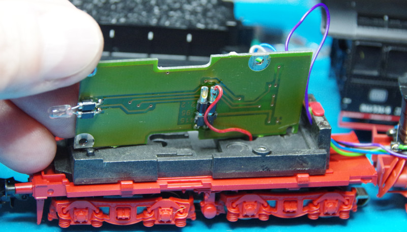
Then I desoldered the board with the Delta electronics. The old radio choke is no longer needed.
The wiring of the CTC module is done according to the following wiring diagram:
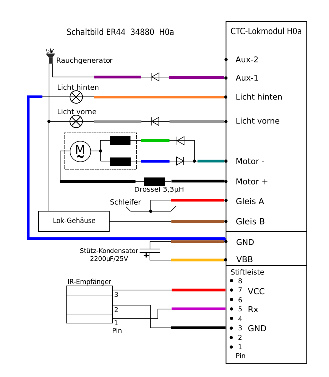
From the accessories for locomotive conversion H0a (CTC No. P2-12-01), the ferrite choke (3.3 uH) is soldered to the black wire that leads directly to the motor. The other end of the choke will be connected later to the motor output of the CTC module.
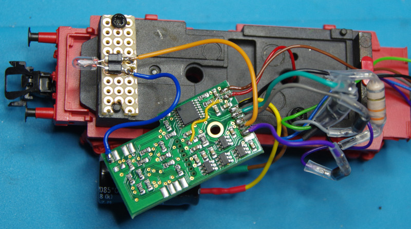
Two diodes are connected to the two wires connected to the field coil (green and blue) in different conducting directions. The other ends of the two diodes are connected together and later connected to the motor output of the CTC module.
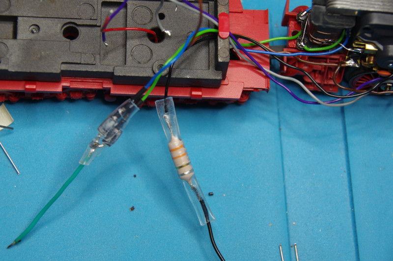
Since one pole of the front light and smoke generator is connected to the locomotive housing, a diode must also be soldered into their supply line (marking ring on the side of the lamp or smoke generator).
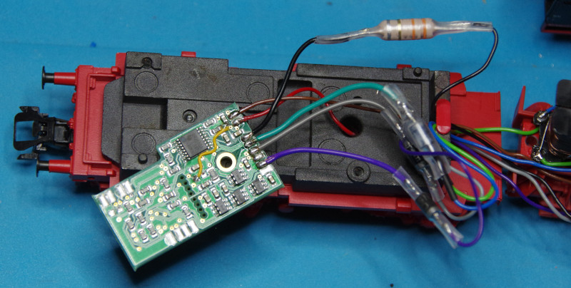
Now connect the track (red and brown), the motor (black and green), the front light (gray), and the smoke generator (purple) to the CTC locomotive module H0a:
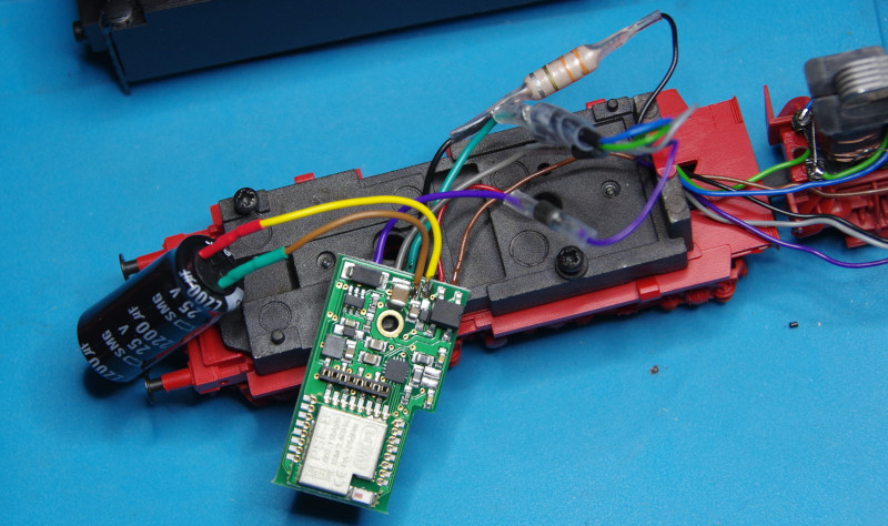
On the back of the CTC locomotive module, the support capacitor is connected (positive pole yellow):
Since the rear light was directly plugged into the Delta board, a new holder must be built for it:
The pickup shoe is located under the tender, thus there is space between the drive axles for the IR receiver. Even a suitable hole for the cables is already in the housing:
