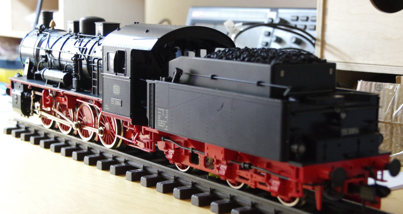
I did my first Gauge-I conversion for a customer who had bought this locomotive used.
Inside, I found a sound decoder from Uhlenlenbrock. The way it was installed, it probably was a conversion by the previous owner:
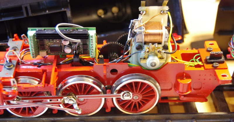
I initially opted for a CTC-locomotive module-G with 3.5 A peak. The first surprise came during motor testing: The locomotive module shut off due to overload. Fortunately, the CTC-locomotive module-G is also available with 6A peak.
The second surprise was the NFC reader. The position below the cylinders seemed ideal:
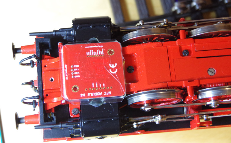
Unfortunately, I hadn’t considered that the NFC reader doesn’t work in direct proximity to metal. It worked in test mode with about a centimeter of distance, but no longer worked when fully assembled.
So a new placement had to be found. Since the tender is made entirely of plastic, that’s a good alternative. I had already solved it this way for the BR50 from PIKO.
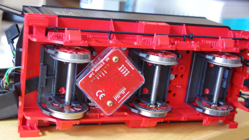
When the locomotive is on the track, the NFC reader is barely noticeable:
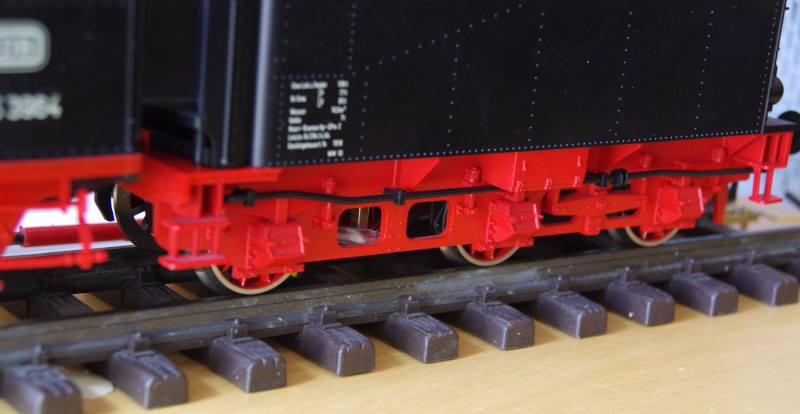
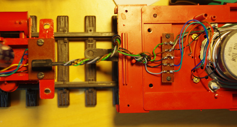
But there was still some tinkering required: The connecting cable between the locomotive and tender has only 5 wires, and I need 4 for the NFC reader plus 2 for the rear lights. The solution was to use a Half-Bridge (HB-1) for the rear lights instead of a LowSide output (SW-2), as it can also switch against VBB (Plus). This allowed me to use the ground line (Minus) jointly for the NFC reader and rear light, and thus the 5 wires were sufficient:
The light configuration had to be adjusted accordingly. Since the configuration is quite specific, I edited directly in the cfg.xml:
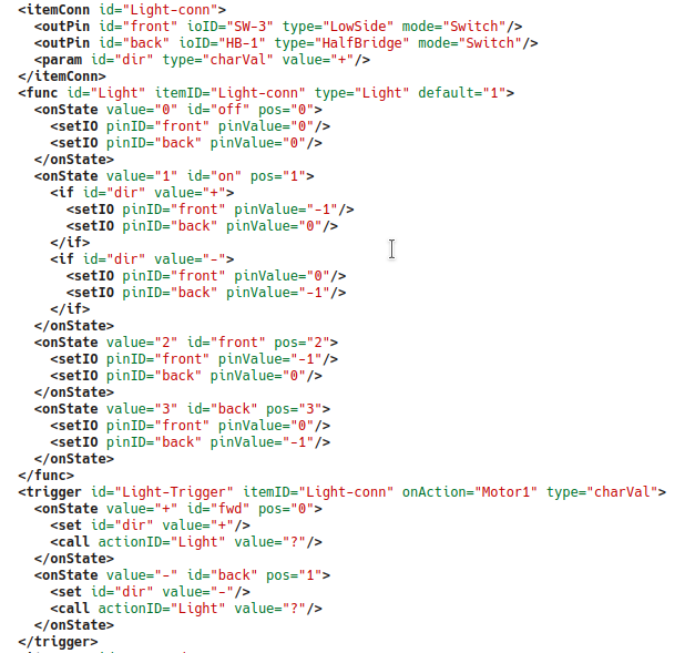
Note: If needed, I can provide this light configuration as a CTC product configuration.
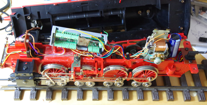
To fit the CTC-locomotive module into the boiler, a beam had to be removed. Then, the converted locomotive looks like this. In the middle behind the locomotive module, you can faintly see the beam that was cut in the boiler:
```


