


This article replaces the old Conversion of LGB Stainz 2020 and 2021 from 2021.
With the “Adapter board PluX22” with screw terminals and the CTC locomotive module M3 for G gauge with PluX22 connector and cables for connecting the NFC reader, converting small G-gauge locomotives has become significantly easier once again.
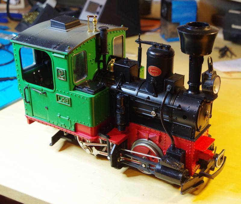
In Dortmund, I was able to purchase a Stainz for 70 EUR from a used dealer, and once again had a 2020 in front of me, where the motor conversion is relatively complex.
As with all old analog locomotives from LGB, the motor in the motor block is directly connected to the track contacts on at least one side. Therefore, before converting to CTC (as well as when converting to digital), a complete disassembly of the locomotive is first required.
Removing the Power Unit
The following articles were helpful during disassembly:
and my old article from 2021.
First, unscrew the chimney, then pull out the front coupling and unscrew the two ladders leading to the cab:
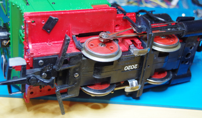
Next, unscrew the upper parts of the control mechanism on both sides:
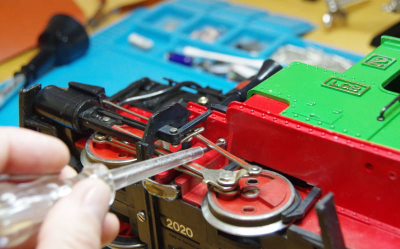
Now, unscrew the piston mounting bracket from the power unit:
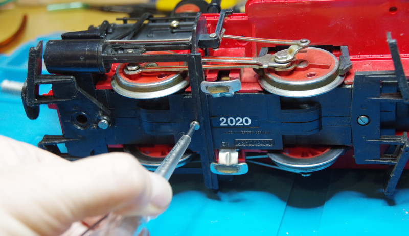
and remove the front track cleaner:
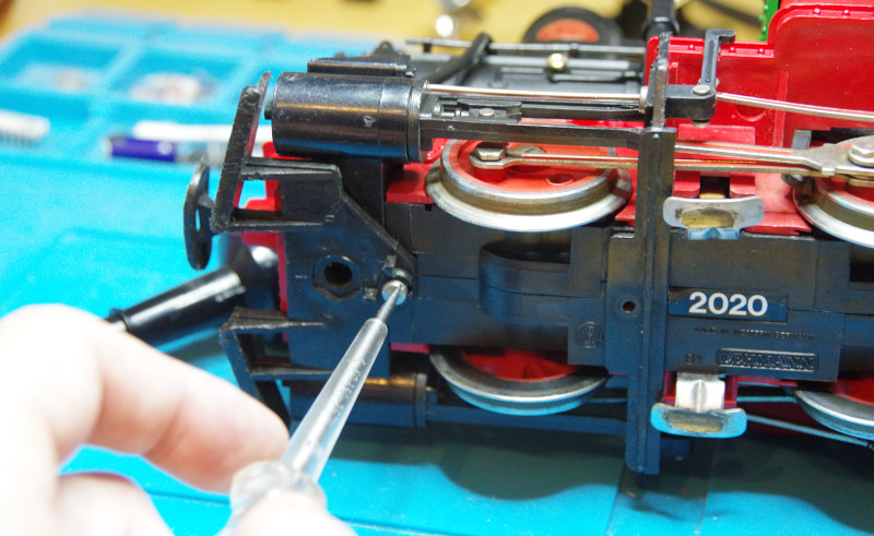
On the right side, there is still a retaining screw for the power unit located beneath the cab:
Bend the control pins outward:
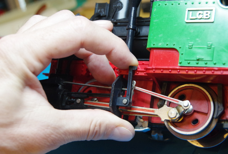
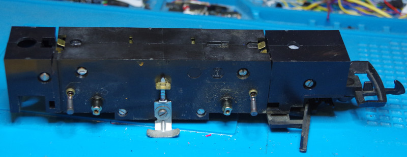
so that the power unit can be pulled downward. In the image, it has already moved the first few millimeters:
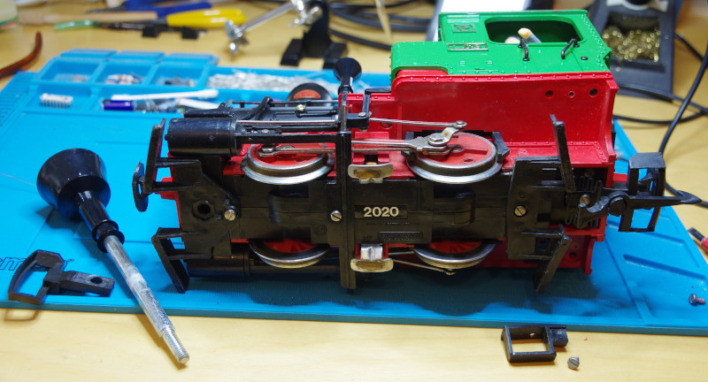
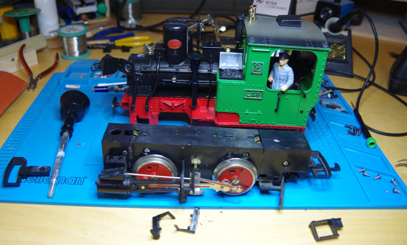
Success—the power unit is now in front of me:
Dismantling the Motor Block
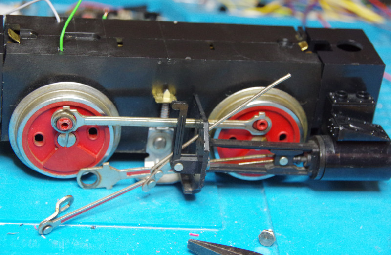
For the 2020 locomotive, the wheels must be removed on one side to open the motor block, and the linkage must be detached for this.
First, unscrew the linkage from the rear wheel:
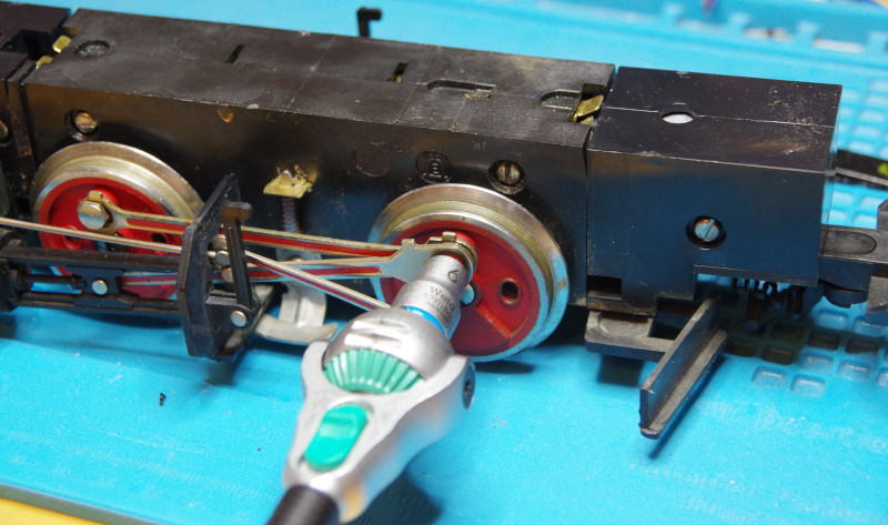
Then from the front wheel:
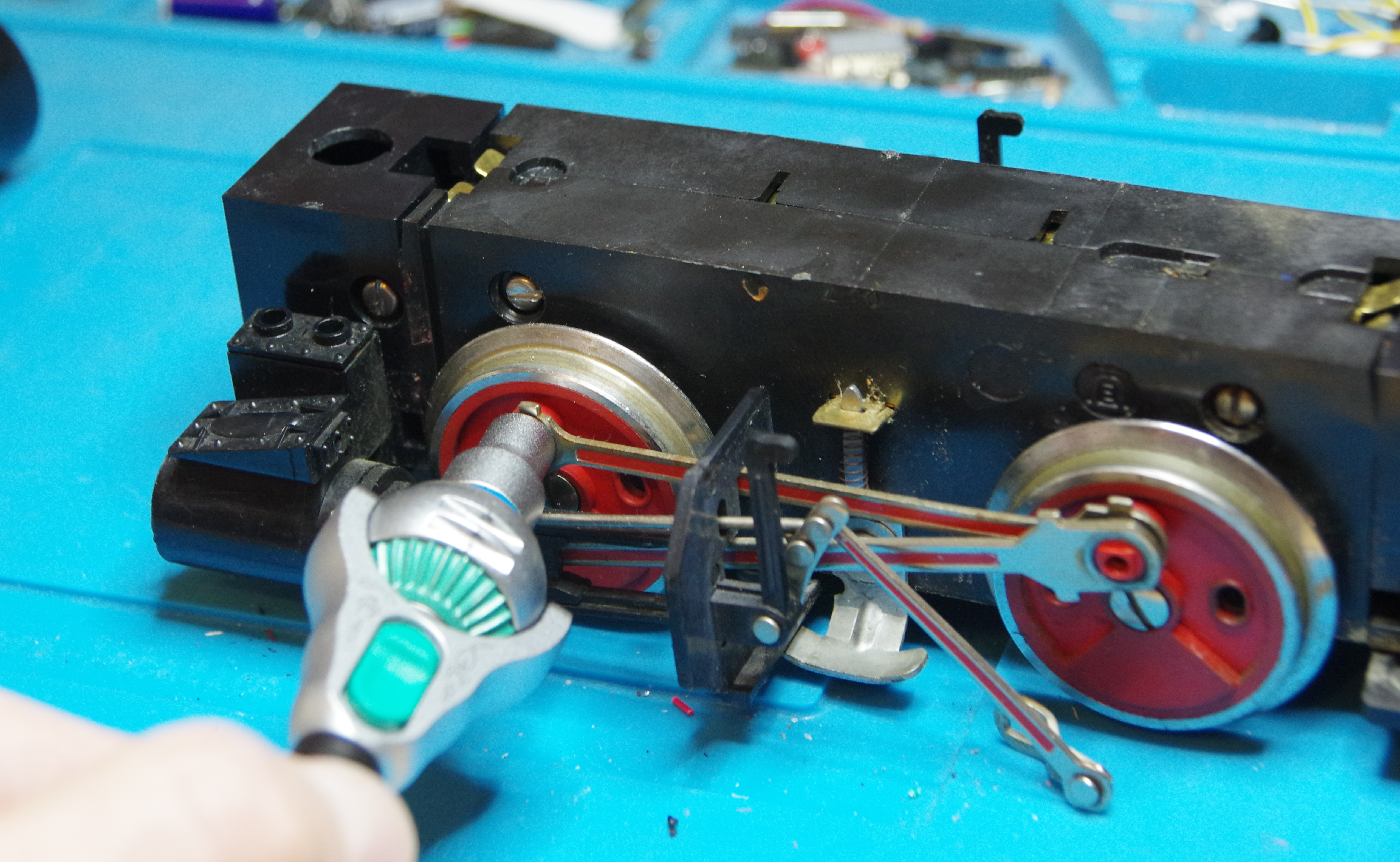
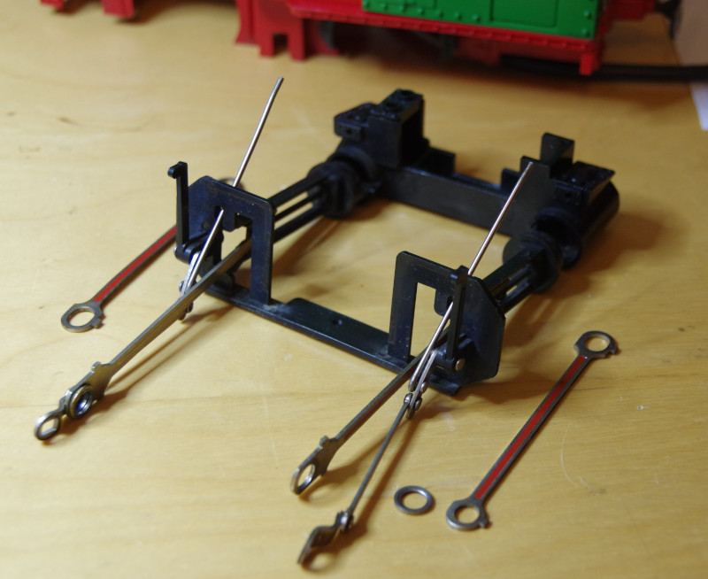
Do the same on the other side and set the linkage with all its parts aside:
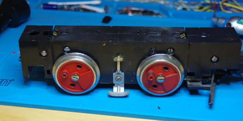
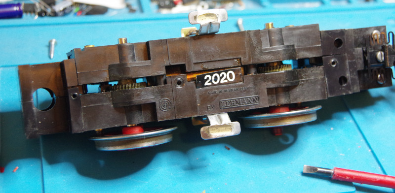
Further disassembly is only required on the left side. Two of the four screws are already visible. The other two are located behind the wheels:
Unscrew the wheels and pull them downward. Ensure that the retaining rings under the screws and the carbon brushes (still protruding in the image) are not lost:
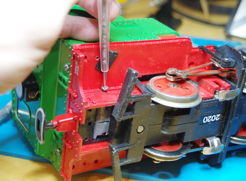
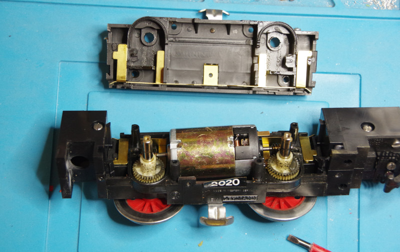
Peel off the label with the article number on one side, then carefully lift off the left half of the housing. A screwdriver can be used for slight leverage on the first section:
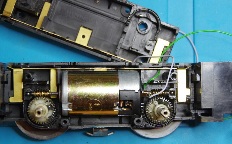
The motor block is now open:
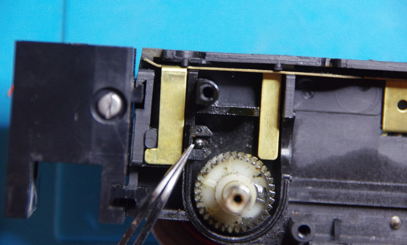
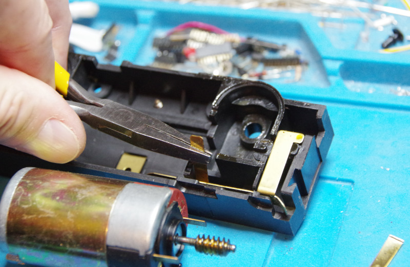
When removing the motor, ensure that the balls at both ends of the drive axle (see tweezers tip) are not lost:
Disconnecting Motor-Track Connections
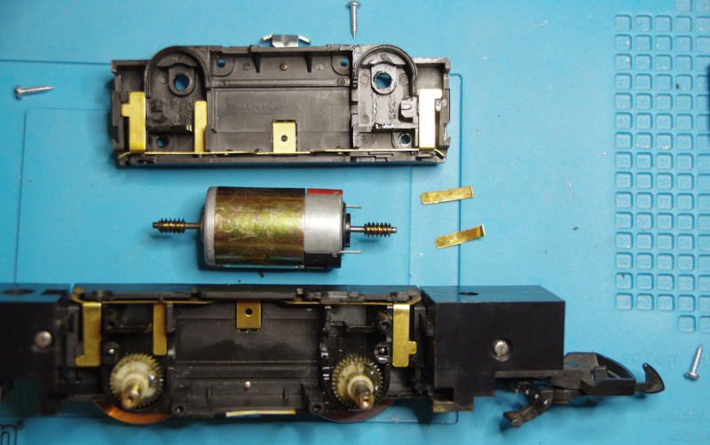
In the 2020 model, each of the two motor halves contains a long, angled metal strip that connects the wheel contacts, pickups, and motor. For the conversion, the connection to the motor must be separated. To do this, the section of the strip leading to the motor contact is detached by bending it back and forth until it breaks off:
The metal strips have been removed and are placed on the right side of the silicone mat in the image. The two previously mentioned balls in the bearings of the drive axle are also clearly visible:
As with the last conversion, I decided to solder the cables directly to the motor contact and route them upward through a (to-be-drilled 2 mm hole) in the motor block. In the image, the screwdriver points to the guide pin on the motor, which must fit into the corresponding recess in the motor block:
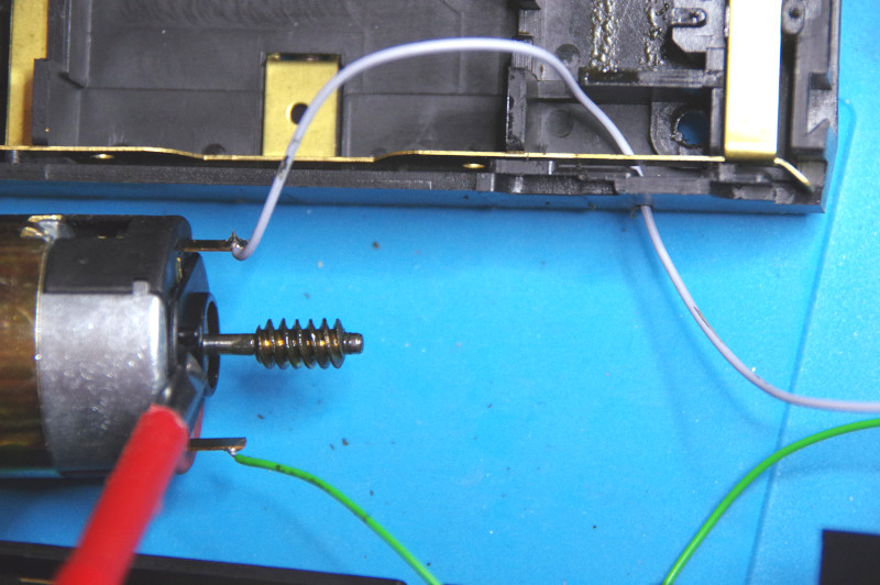
I chose the position of the hole so that the cable exits through a gap in the locomotive frame above it. The following image shows the position clearly:
When routing the cables, ensure they cannot be caught by the gear mechanism. In the image, the motor is placed back in the right half of the motor block, and both balls remain in their correct positions:
Assembly
To ensure the linkage functions properly again, the wheels must be aligned so that they are positioned evenly at the front and back. For this, I used the balance weight triangle on the wheel (right side of the locomotive) as a reference point. Once the housing is assembled, you can also test the individual rods of the linkage to see if the wheels can rotate without obstruction. This time, it took me three attempts before it worked. In the image, the linkage is already reinstalled:
Mount the rear crank so that its center aligns with the wheel axle:
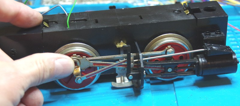
I had remembered assembling the linkage as a “nightmare,” but it turned out to be completely trouble-free.
Wiring
Now that the motor is prepared for the CTC upgrade, it’s time for the wiring.
I soldered cables to the two metal tabs protruding from the back of the motor block and removed the contact screws from the locomotive frame. In the image, all cables leading to these screws have already been disconnected from the locomotive frame. We no longer need the diode board in the center of the image.
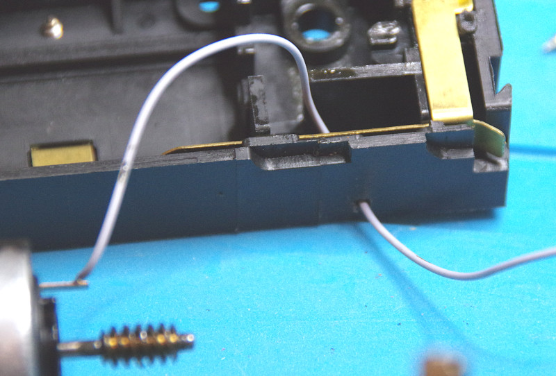
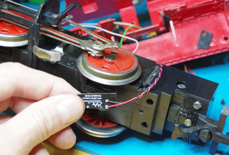
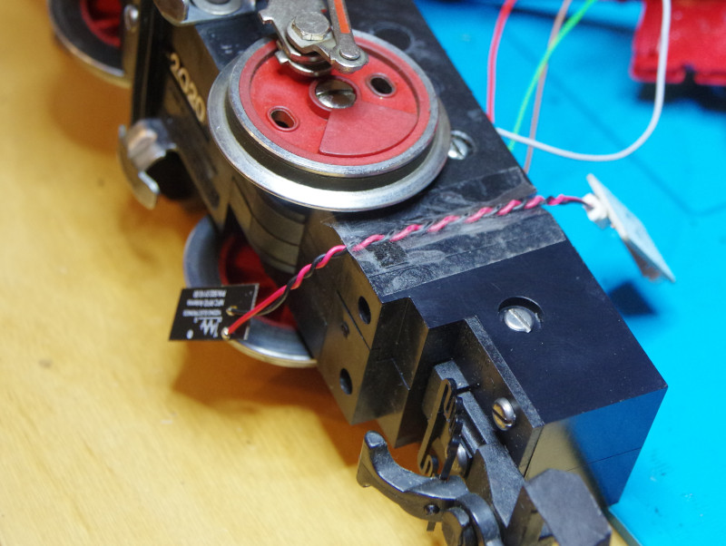
For the NFC reader’s antenna, I carved a cable channel into the motor block with a utility knife to prevent the cable from being pinched by the locomotive frame later:
Tesa tape is surprisingly good for securing cables:
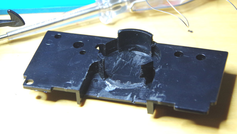
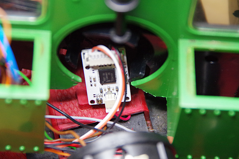
Now I can’t avoid some “carving” on the housing. Part of the guide on the control panel toward the boiler had to be removed to make space for the NFC reader—the antenna cable should not be lengthened or shortened.
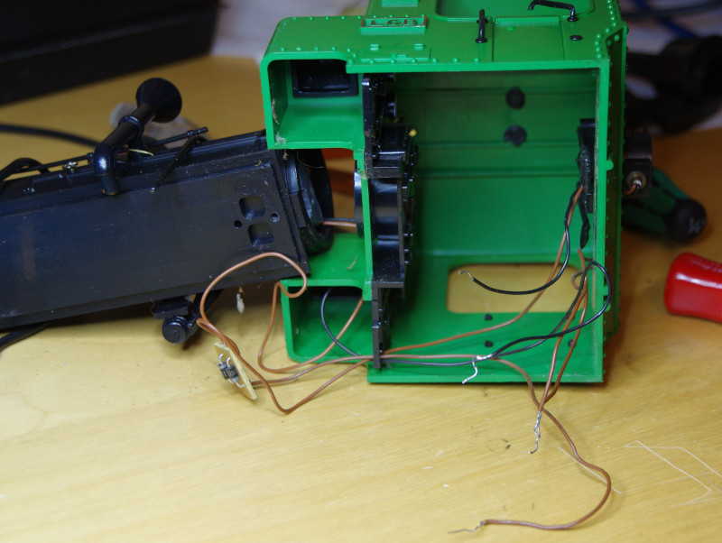
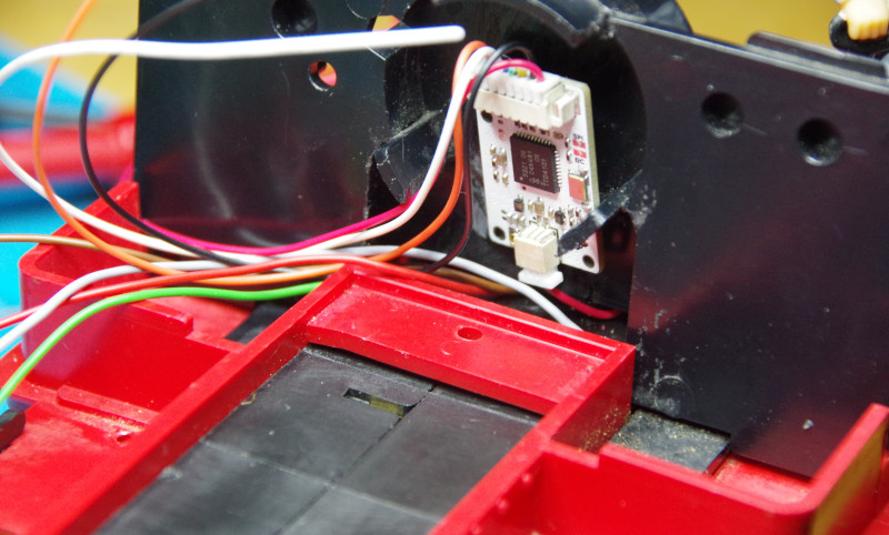
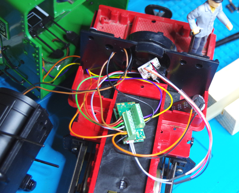
The next image shows the control panel mounted on the chassis with the NFC reader (white circuit board) and the cables routed toward the water tank from the motor, track, and NFC reader. I plan to install the CTC locomotive module in the water tank.
Then I soldered suitable cables to the rear lamp and the rear power connection (switchable via AUX1). The positive pole (orange) is shared and will later connect to VBB on the CTC locomotive module. The negative pole (yellow for the taillight, purple for AUX1) is switched individually.
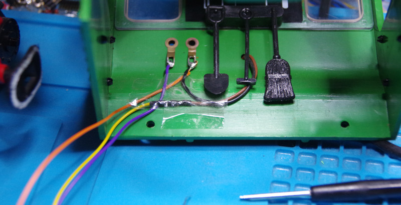
The capacitor (2200 µF) goes into the coal box. In the image, the front light cables are still routed through the control panel. I later changed this and ran them through the newly created cable channel at the bottom of the control panel. In this state, I performed the first test on the roller test stand.
To make my cable channel work, I also had to remove quite a bit from the cab:
Ideally, I would have removed enough so that the cab could be placed over the mounted boiler and control panel. As it was, assembling these three parts without pinching any cables was quite fiddly.
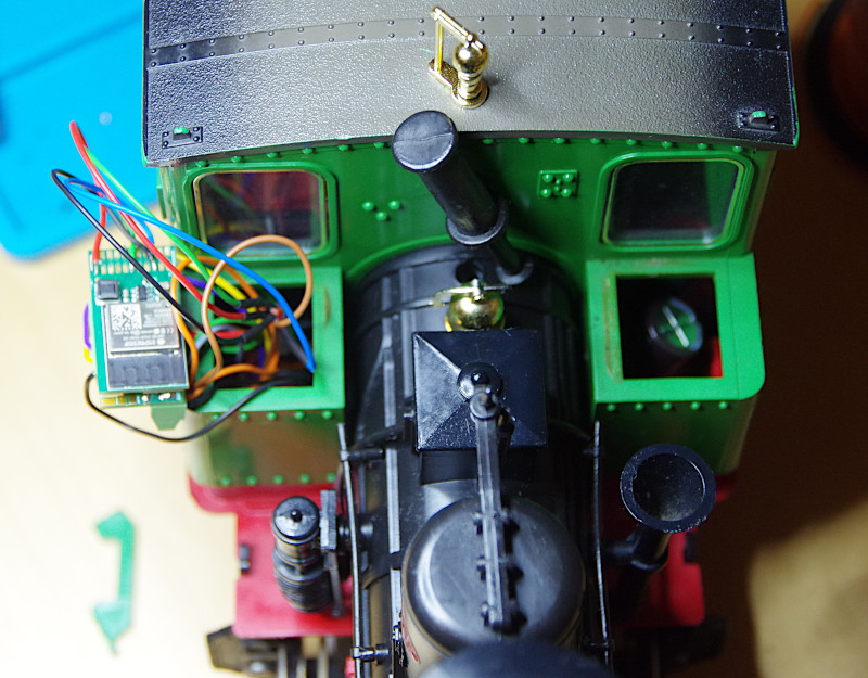
For assembly, I threaded the locomotive module, adapter, and all excess cable lengths through the top cover of the water tank. Good thing I made the cables relatively long.
By the way, in the image, you can see the separated housing part on the bottom left of the workbench. On the right, in the coal box, you can see the buffer capacitor:
Stuffing the cables and adapter into the cable box was straightforward.
Now, a few more tests with the new (small) NFC reader are pending, and then it will also be available for order in the online shop.