





Introduction
A CTC starter set in combination with an expansion set enables the construction of a small layout on which the essential capabilities and features of CTC can be tested and used. Although this is "only" a starter set, the layout is designed to be expandable. These expansions will be described in additional documentation as they become available. The construction of the starter set already takes expansions into account with the assigned names, and relevant points will be highlighted where necessary.
This documentation describes the starter set plus expansion set for Märklin C-track. The modules must be installed and configured in the locomotives and turnouts. If a starter set with pre-installed CTC-Loco-Modules and CTC-Turnout-Modules is used, the installation steps can be skipped.
Two semaphore signals with magnetic drives are also used. The following topics are covered initially:
- Installing and electrically connecting modules (locomotives, turnouts) (Chapter 2),
- Constructing the layout (Chapter 3),
- Configuring turnout modules for operating turnouts and semaphore signals (Chapter 4),
- Creating the track diagram (Chapter 5), and
- Initial commissioning of the layout (Chapter 6).
The track layout to be constructed is similar to that described in the article Creating a CTC Model Railway . The associated CTC-App software can be installed and run on Windows, Linux, and Mac. Please note any possible restrictions regarding the operating systems. Different Linux distributions may exhibit divergent behavior. More information on supported versions can be found in the operating instructions Chapter 2 .
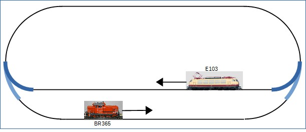
The track plan consists of an oval with a station as a stop. For train operations, it is assumed that one locomotive travels clockwise and another travels counterclockwise. The CTC-App is used to switch turnouts and control the locomotives.
Once the locomotives have run on the layout for the first time, the expansion of the layout can begin:
- Installing and configuring IR beacons (formerly called "IR transmitters") in the tracks (Chapter 7),
- Adding IR beacons to the track plan (Chapter 7),
- Calibrating locomotive sensors (Chapter 9), and
- Operating trains with signals and IR beacons (Chapter 10).
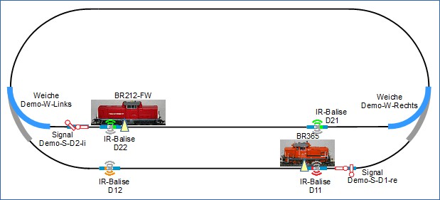
The following functionality is implemented: when a signal is set to "Stop," the locomotive slows down, travels to the IR beacon in front of the signal, and stops. This functionality is extended with the beacons.
Names are chosen for the beacons, signals, and turnouts that are useful or even necessary for block operation and automated train control (for a more detailed explanation, see "Outlook").
The next step is to introduce automated train operation. With this configuration, a small "timetable" is created for a locomotive:
- Entry into the station area with the locomotive always slowing down (Chapter 10),
- Slow travel into the station and stopping (Chapter 10),
- After the predefined stopping time, the locomotive continues its journey, completes a lap, and re-enters the station area (Chapter 10).
Outlook
For further expansion of the layout, the starter set is extended:
- A turnout and additional track enables a "stub-end station."
- Additional IR beacons expand the block operation.
- Some blocks are equipped with semaphore signals.
- Corresponding CTC modules are required for the IR beacons, semaphore signals, and turnouts.
With the mentioned expansions, train operations are extended to the stub-end station. The following diagram shows the schematic track plan in a very extensive expansion stage. Which individual beacons, signals, turnouts, and tracks are used in each construction example will be specified accordingly.
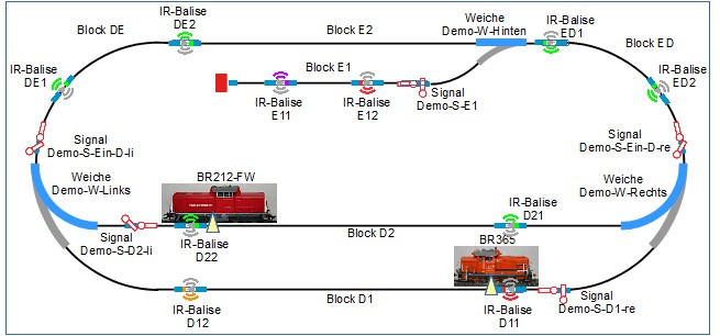
As with the beacons, signals, and turnouts, names are chosen for the tracks and blocks that are useful or even necessary for block operation and automated train control. There are two station areas, designated as "D" and "E." This results in the following blocks:
- Block D1 is the "through area" of "station area D."
- Block D2 is the "stopping area" of "station area D."
- Block E1 is the "stopping area" of "station area E," which is designed as a stub-end station.
- Block E2 is the "through area" of "station area E."
- Block DE connects block D to block E. The designation assumes the direction of travel of a locomotive in a clockwise direction.
- Block ED connects block E to block D. The designation assumes the direction of travel of a locomotive in a clockwise direction.
- Beacons are numbered clockwise and assigned to a block.
- Beacons D21 and D22 belong to block D2 and are closely related to the position of the associated signal Demo-S-D2-li.
- Beacons D11 and D12 belong to block D1 and are closely related to the position of the associated signal Demo-S-D1-re.
- Beacons DE1 and DE2 belong to block DE and are closely related to the position of the associated signal Demo-S-Ein-D-li.
- Beacons ED1 and ED2 belong to block ED and are closely related to the position of the associated signal Demo-S-Ein-D-re.
- Beacons E11 and E12 belong to block E1. Beacon E12 is closely related to the position of the associated signal Demo-S-E1.
- Signals, like beacons, are part of a block. Signals can be considered as "exit signals from a block" or as "entry signals into the next block" (in the direction of the traveling train).
- Signal "Demo-S-D2-li" is an exit signal for block D2, locomotive BR212-FW travels clockwise and later in shuttle train operation.
- Signal "Demo-S-D1-re" is an exit signal for block D1, locomotive BR365 travels counterclockwise.