Contents
1. Basic Concept1.1. Controlling Locomotives
1.2. Locomotive Functions
1.3. Locomotive: Autopilot
1.5. Control panel: Switching turnouts, signals, ...
1.6. Track diagram: Switching and status displays
2. App Installation
3. Wi-Fi
3.1. Connecting Modules to Wi-Fi
3.2. Factory New Modules
3.3. Status Indicators of the Modules
3.4. Wi-Fi Monitor
3.5. Statistics
4. Configuring Modules
4.1. Config - Connect Products
4.2. Config - Actions
4.3. Config - Linking Actions
4.4. Config - Editing Actions
4.5. Config - Editing Scripts
4.6. Config - Connect DCC decoder
5. Configure the engine
5.1. Motor-Sensor Calibration
5.2. Adjusting the Motor
6. Track Diagram Control Panel
6.1. Edit Track Plan
6.2. Editing the Model Railway
6.5. Balises (ID Transmitters) in the Track Plan
7. Automation
7.1. Automation: Blocks
7.2. Automation: Driving Routes
7.3. Automation: Driving Orders
7.4. Automation: Timetables
8. Old Digital: Bridge to DCC & Co.
8.1. Old Digital: Integrating DCC Decoders
8.2. Old Digital: Integrating Z21 Control Center
8.3. Using Z21 Hand Controller
8.4. Model Railway Control Software via Z21
9. Sound
9.1. Sound with SUSI Interface
10. Wagon Recognition (Axle Counter)
10.1. Configure Wagon Detection
10.2. Engine Facility (BW)
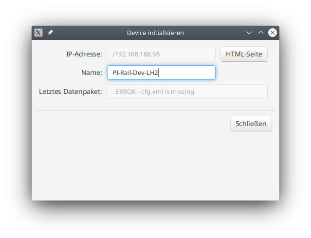
A1. Appendix - Error Handling
A2. Appendix - HTML Page
A3. Config - Create Product Catalog
A4. Cable Colors
B.01. Appendix B: Examples
B.02. Config Example: Timed Stop
B.03. Config Example: Signal Dependent on Turnout Position
B.04. Config Example: Balise Dependent on Turnouts and Signal
B.05. Configuration Example: Track with Signals for Both Directions
1. Basic Concept
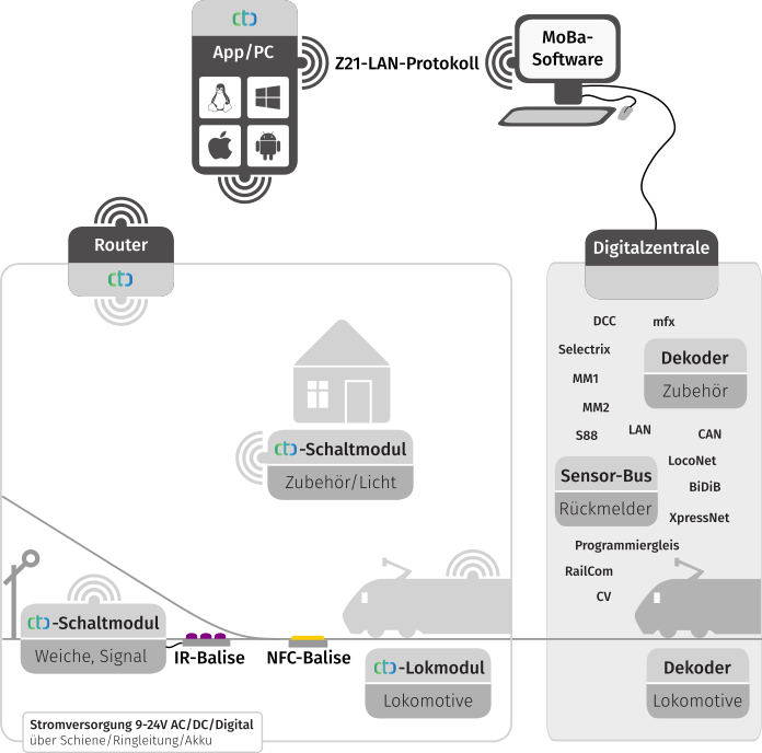
CTC is a hardware and software system for controlling model railways. It contains the following characteristics:
- CTC Modules: Electronic assemblies for controlling locomotives, turnouts, signals, lighting, action blocks, etc. Local firmware and configuration handles local control tasks such as motor control, turnout switching, lights on/off, etc. on each CTC module. The respective configuration is stored decentrally in the corresponding CTC module.
- CTC App: This software serves as a user interface (graphic user interface) and can be used on a smartphone, a tablet with Android or iOS, or also on a PC with Windows, MAC or Linux. A dedicated and costly special central control unit is not required.
- CTC Modules are configured via the CTC App.
- Communication via Wi-Fi: Communication between the CTC app and CTC modules, as well as between the CTC modules themselves, takes place via a dedicated Wi-Fi access point (for instance, a FritzBox). The transmission speed is up to 54 Mbit/s. Apart from the power supply, no additional cabling is necessary.
- The CTC modules are addressed via the CTC App. The graphical user interface enables, for example, the control of driving speed, turnout settings, signal lights, etc.
- Exact Position Detection: The CTC App can determine the exact position with the help of dedicated infrared transmitters in the tracks and infrared receivers in the locomotive for small tracks (up to 0 gauge). For 1 gauge and larger, the same is achieved with NFC tags in the track and an NFC reader under the locomotive.
- Wagon recognition (axle counting): Starting from CTC App 4.22, an NFC reader can be installed under the track in order to recognize wagons equipped with NFC tags. Therefore, CTC provides an adequate substitute for axle counters - with the advantage that the app exactly knows which wagon has just passed by.
- Sound is possible with CTC using SUSI3 or a DCC sound decoder.
- Parallel operation with other “market common” digital and analogue systems is possible, e.g., via the Z21 LAN protocol.
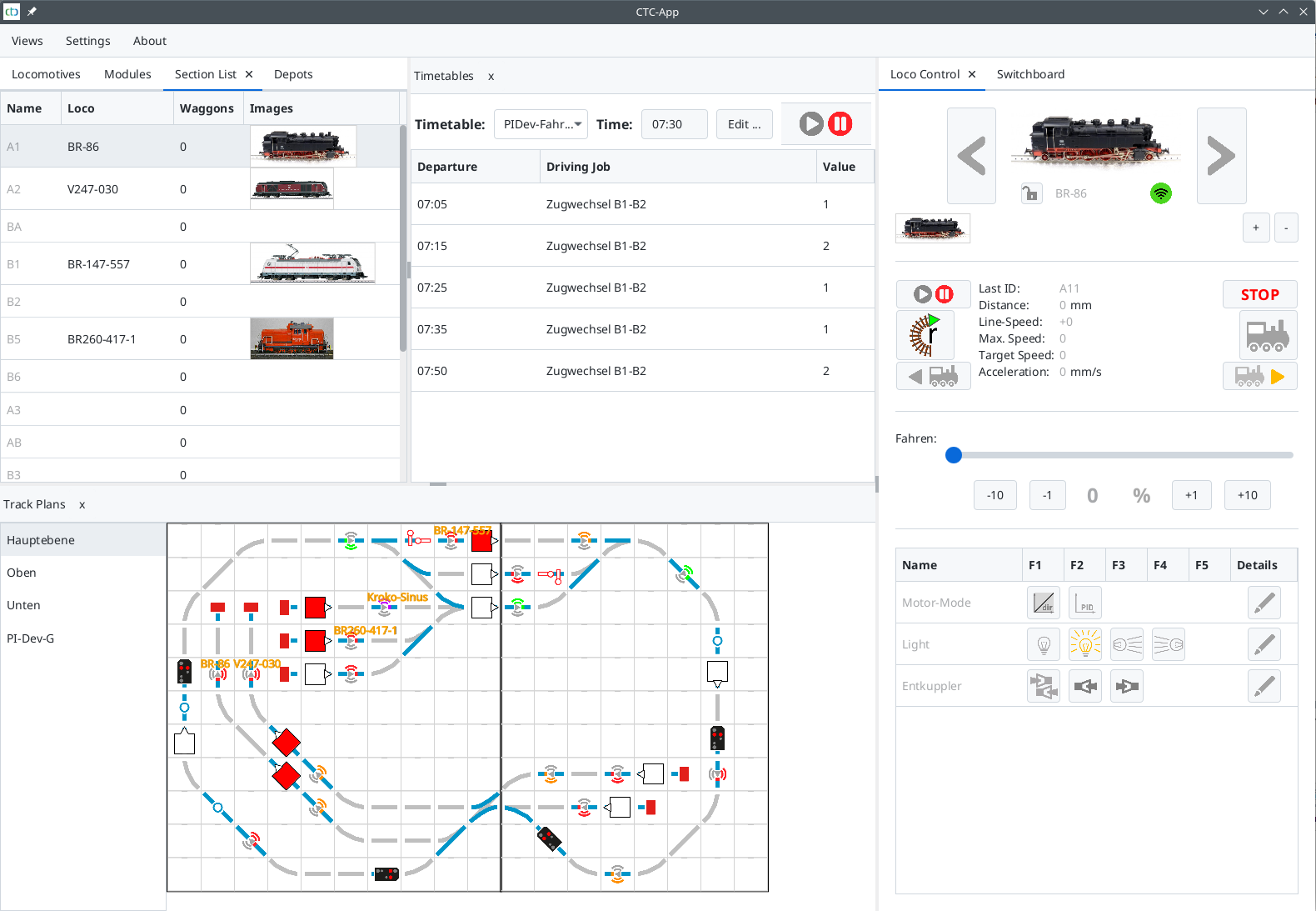
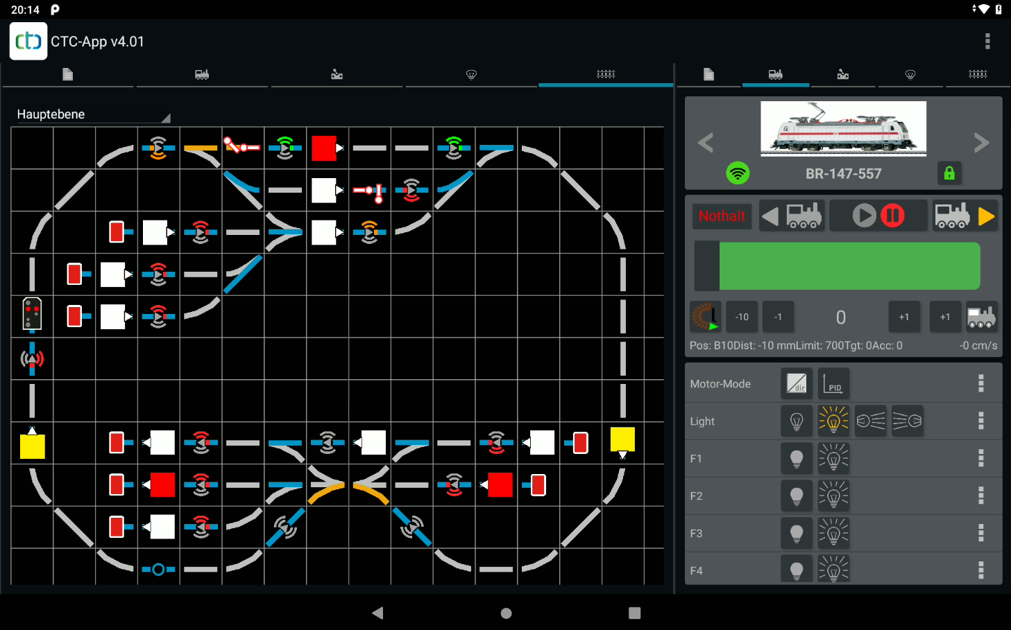
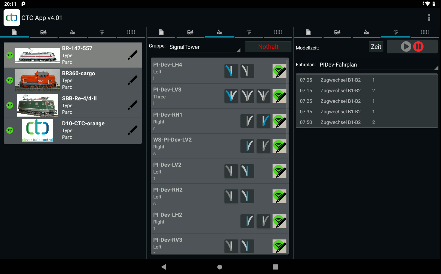
Views of the App
The CTC app consists of a whole range of views. In the desktop app, these can be freely arranged in the main window and additional windows, and can also be distributed across multiple screens. The mobile phone and tablet app have a largely rigid layout.
The following views are available:
- The Module List shows all CTC modules that have reported to the app since its launch.
- The Locomotive List shows all locomotives that have reported to the app since its launch.
- The Locomotive Control provides all functions for manual control of a locomotive.
- The Control Panel lists all turnouts, signals, … and allows you to switch them.
- The Sensor Display shows all sensors and their status.
- The Track Layout shows the model railway with all placed track layouts.
- The Block List shows all blocks with the locomotive and its wagons located there.
- The Timetable Display shows a selected timetable for automatic operation.
- The Engine Shed Display shows engine sheds and wagons registered there.
In the desktop app, new views can be opened as new windows via the “View” menu. You can then move the view to a different location by clicking on the title of the view and dragging the view to the desired location while holding down the mouse button. Gray rectangles visualize where the view will be “docked” while dragging.
The following pictures show the CTC app once on a PC and twice on an Android tablet:
1.1. Controlling Locomotives
Driving
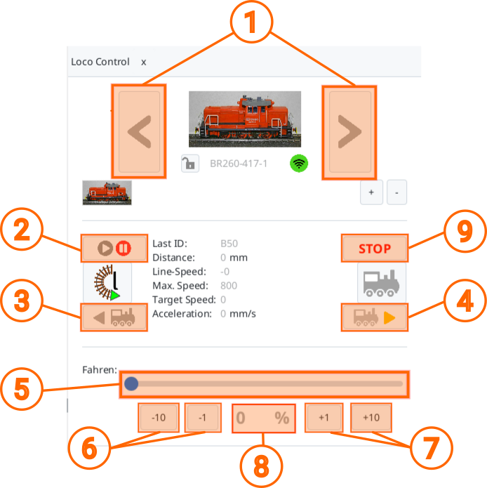
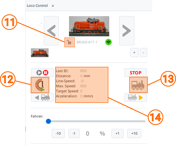
With the following buttons and displays, you can control the displayed locomotive:
- With (1) you can switch between the available locomotives, i.e. select a different locomotive.
- With (2) the locomotive is activated (blue) and paused again (red). When activated, the set direction of travel (3)/(4) and speed (5) are set, i.e. if the slider (5) is on a value greater than zero, the locomotive starts moving.
- With (4) you activate the forwards driving direction, with (5) backwards. In both cases, clicking on the button also sets (2) to active (blue). The set direction of travel can be identified by the coloured arrow in the button: yellow for forwards, red for backwards.
- With (5) you set the speed. The set value is displayed as a number (8) underneath.
- With (6) the speed is gradually decreased and with (7) increased.
The picture and name of the locomotive can be changed via their configuration. Both are stored in the locomotive.
Additional Features and Displays
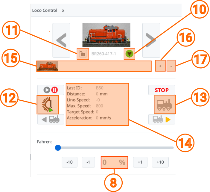
- The Wi-Fi symbol (10) indicates whether the locomotive is currently reachable (green), has not responded for more than 3 seconds (yellow), or for more than 10 seconds (red). In addition, the green Wi-Fi symbol shows the signal strength, see also Chapter 3 “WiFi”.
- To the left of the locomotive name, the locomotive status (11) is displayed, the individual symbols are described in Chapter 1.3 “Autopilot”.
- If your locomotive has an IR receiver, you can adjust the orientation of the locomotive with (12): r = clockwise, l = counter clockwise. This is important so that the locomotive only stops in front of a red signal when approaching from the front. After crossing two balises of the same block, the locomotive sets its orientation itself and the symbol on the button may be adjusted.
- (13) toggles the automatic operation on and off. An “A” on the button indicates activated automatic operation. When a locomotive is forced to decelerate/stop in front of a red signal by a balise, the automatic operation activates itself, which can then be seen from the symbol on the button.
- In the middle (14), there are some additional status information about the locomotive, which will be addressed at the appropriate point in this documentation.
1.2. Locomotive Functions
The locomotive functions are located in a table below the locomotive control:
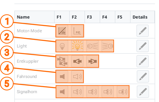
The functions a locomotive offers are set in the configuration of the locomotive. Each function configured there shows itself with up to 5 buttons for the different states of the function. The currently active state is highlighted in color.
The factory-configured headlight (2) in the CTC locomotive modules has the following states (in the picture from left to right):
- Light off
- Automatic light: The headlight burns at the front or rear depending on the direction of travel
- Front light on
- Rear light on
The Motor-Mode (1) is also pre-configured in all CTC locomotive modules:
- The left button activates the normal mode.
- With the right button the load regulation in the form of a PID controller can be activated. The necessary condition for this is that the motor sensor has been calibrated.
The image also shows examples of functions added via the configuration of the locomotive:
- With (3) the decoupler can be deactivated, as well as activated at the front and rear.
- With (4) the drive sound can be switched on and off.
- With (5) four different signal horn sounds can be played.
1.3. Locomotive: Autopilot
Unlike traditional digital systems, with CTC the locomotive always controls itself. Only target values for the speed are given via the CTC app.
For every locomotive with an ID reader, even with manual control, there is already some automation:
- If the locomotive driver exceeds the maximum permissible speed, the locomotive will automatically reduce its speed.
- If the locomotive driver ignores a red signal, the locomotive will trigger an emergency braking.
Since the locomotive can’t see by itself, speed limits and signal states have to be communicated to it using balises. If you’ve ever dealt with the European Train Protection System ETCS, you’ll notice remarkable parallels to CTC.
Beyond these simple train protection measures, there is also the possibility to activate an autopilot.
The autopilot has the following modes:
- Travel with a given maximum speed, observing speed limits and signals.
- Timetable-based travel
Before driving with autopilot, the locomotive should know its orientation on the track. If the symbol on the button (12) shows an “r” (clockwise) or “l” (counterclockwise), the locomotive knows its orientation.
By clicking on the button (12), you can set or change the orientation.
Note: When the locomotive has passed two balises of the same block, it knows its orientation. The button then displays it.
Travel with a preset maximum speed
This operating mode is activated by manually setting the locomotive to the desired maximum speed and then activating the autopilot (13). Afterwards, the locomotive continues to drive autonomously until the autopilot is terminated again.
The locomotive never travels faster than the speed set when the autopilot was activated:
- If a speed limit is communicated to the locomotive via a balise, it reduces its speed. If the speed limit is lifted again, the locomotive accelerates back to the set maximum speed.
- If a red signal is communicated to the locomotive via a balise, the locomotive autonomously stops in front of the signal. If the signal turns green again, the locomotive autonomously resumes its journey.
- If a stay is communicated to the locomotive via a balise, the locomotive stops for the time indicated by the balise. After that, the locomotive continues its journey.
- If a turning point is communicated to the locomotive via a balise, the locomotive stops for the time indicated by the balise.
After that, the locomotive resumes its journey in the opposite direction.
Scheduled Journey
The scheduled journey is activated by turning on the autopilot (13) on a stationary locomotive. Subsequently, a schedule is started that begins in the block where the locomotive is currently located. The CTC app then sends the schedule to the locomotive, which starts processing it.
A schedule consists of a chronological sequence of balises that the locomotive must pass. A command can be assigned to each balise, which the locomotive executes, provided it is not in contradiction with the command sent from the balise. That means speed restrictions and signal statuses sent by balises are also taken into account in this mode of operation.
Locomotive States (11)
The state (11) of the locomotive control is shown in the line below the locomotive symbol. The locomotive can take on the following states:
| Symbol | Name | Definition |
|---|---|---|
 |
Free | The locomotive is stationary and is free for manual control. |
 |
Manual | The locomotive is manually controlled by you. |
 |
Other | The locomotive is manually controlled by another person or by another CTC app. |
 |
Halt | The locomotive has recognized a red signal and is either slowing down or has already stopped before this signal. The locomotive will continue as soon as the signal clears its way. |
 |
Limit | The locomotive has detected a speed limit and may reduce its speed. |
 |
Stop | The locomotive is braking to stop at a station. |
 |
Reverse | The locomotive is braking to stop at a terminus, then it will continue to drive in the opposite direction. |
 |
Pause | The locomotive has stopped at a station with “Stop” and will continue to drive after the stay. |
 |
Pause-Rev | The locomotive has stopped at a station with “Reverse” and will continue to drive after the stay. |
 |
Continue | The locomotive continues its journey after “Stop” or “Reverse”. Once it has finished accelerating, it switches to “Autopilot”. |
 |
Autopilot | The locomotive drives automatically without any speed limit. |
1.5. Control panel: Switching turnouts, signals, ...
Through the “Control Panel” tab, you can access the buttons for switching turnouts, signals, …:
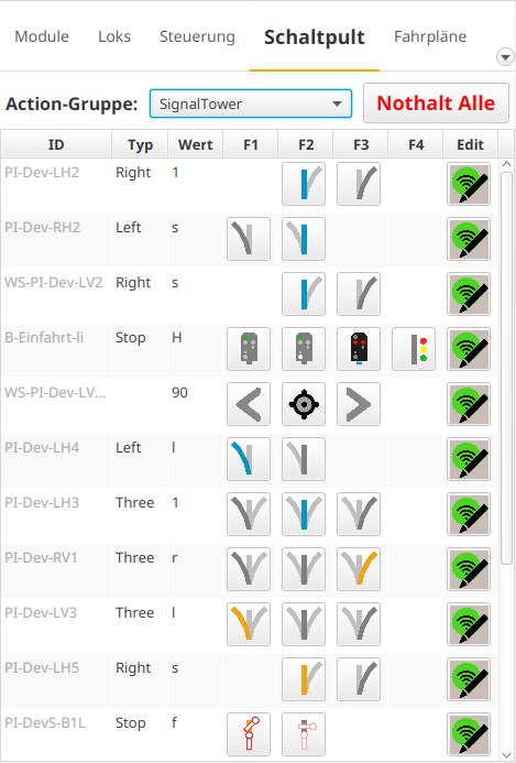
The switching functions are divided into groups. These are pre-set via the Product Catalog, but can be customized as needed in the CTC-App’s configuration. Adding new groups is also possible.
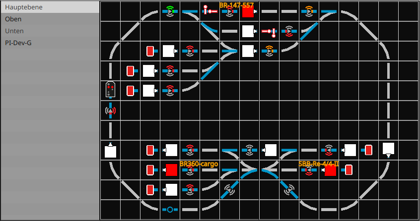
1.6. Track diagram: Switching and status displays
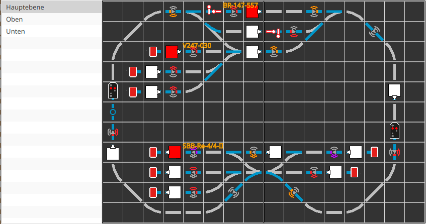
In the CTC PC apps, you will find the track diagram at the bottom of the window, on tablets and smartphones as a tab with the track symbol.
You can learn how to create a track diagram in Chapter 6 - Track Diagram Interlocking.
On the left side of the view, you can see a list of all available track sections. In the example, the model railway is divided into a left (top) and right (bottom) half. The “main level” combines both halves and is therefore suitable for tablets and PCs. “Top” and “Bottom” are more suitable for narrower smartphone displays.
All blue track pieces are associated with an action. This can be either a switching action (turnouts, signals, …) or a sensor (balise, block, …).
Turnouts and Signals
The symbols for turnouts and signals are identical to those on the switchboard. The symbol reflects the current state of the turnout or signal. If the symbol is coloured orange, it is reserved for a route and cannot be switched.
When you click on a turnout or signal, it will switch to the next state, according to the order shown on the switchboard from left to right.
In the PC app, you can open the module’s Config-Dialog, where the turnout or signal is configured, by right-clicking.
Sensors
Classical sensors do not currently indicate any state.
In the PC app, you can open the module’s Config-Dialog in which the sensor is configured by right-clicking.
Balises
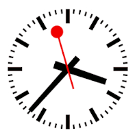
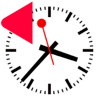
Balises indicate the state of the balise through coloured symbols. The small arrow in the center of the symbol indicates the clockwise direction (arrowhead is on the right). The symbol applies to the direction of travel indicated by the coloured arcs on the right side (in the direction of travel).
| Symbol | Color | Commands | Meaning |
 |
gray | Balise is not assigned or the corresponding CTC module is not active. | |
 |
gray | - | Balise is active, but does not send a command to the locomotive. |
 |
green | ‘F’, ‘f’ | Balise is active and sends the command for free travel. |
 |
yellow | ‘W’, ‘w’, ‘L’, ‘l’ | Balise is active and sends the speed limit command. |
 |
orange | ‘M’, ‘m’ | Balise is active and sends the slow down command. |
 |
red | ‘H’, ‘h’, ‘S’, ‘s’, ‘T’, ‘t’, ‘E’, ‘e’ | Balise is active and sends a stop command. |
 |
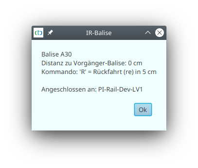
purple | ‘R’, ‘r’ | Balise is active and sends the reverse command (from CTC-App 4.08) |
Details about the commands can be found in the section “Commands for Locomotives/Signals” in Chapter 4.5 - Edit Script.
In addition, a balise can be clicked to find out its exact state:
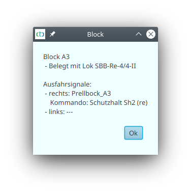
Blocks
Blocks are represented as colored filled rectangles. The small arrow at the edge of the rectangle indicates the clockwise direction (arrowhead is on the right).
| Symbol | Colour | Meaning |
 |
grey | Block is not assigned or the associated CTC module is not active. |
 |
white | Block is active and not occupied |
 |
yellow | Block is active and has been reserved by a route |
 |
red | Block is active and occupied by a locomotive |
A block can be clicked to find out its exact status:
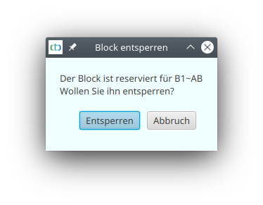
On the PC, a reserved block can be released again by clicking with the right mouse button:
2. App Installation
Tablet and Smartphone
The apps for Android and iOS are installed via their respective app stores (each with a fee of 9.99 EUR):
- Android app via Google Play Store
- iOS app via App Store
Note: We decided to charge a fee on the Play Store to reduce unnecessary downloads and resulting evaluations.
Linux, Mac and Windows
You can find installers for the PC application for Linux, Mac OS/X and Windows in our Download section. The installers create appropriate start menu entries each time.
Python
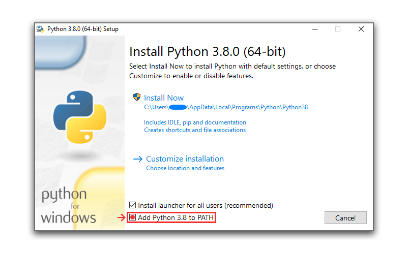
In order to be able to carry out firmware updates of the CTC modules, you will need an up-to-date Python, for example version 3.8. Under Linux, it should always be available, but under Windows, it needs to be installed separately.
When installing Python on Windows, it is important to ensure that the box for “Add Python 3.8 to PATH” is checked.
MacOS/X
If MacOS/X denies the installation, this could be due to a missing internet connection - the signature requires online access.
Linux
If Linux refuses the installation, then open with the “QApt package installation program” or install via command line, for the CTC-App version 4.24 for example.
sudo apt install ./ctc-app_4.24_amd64.deb
Windows
Windows 10 sometimes complains about a missing signature:
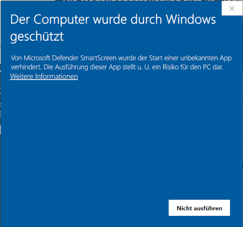
Then simply click on the “More information” link. This will display the “Run anyway” button:
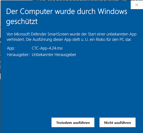
Now you can click on “Run anyway” to install the CTC app.
3. Wi-Fi
This chapter covers everything related to the configuration, setup, and optimization of Wi-Fi.
Basics
Getting started with CTC modules and their Wi-Fi often proves to be a major hurdle. For this reason, we begin here with a few basics.
Fundamentally, CTC uses the standard functionality of Wi-Fi. The term WLAN is only commonly used in German and is too generic — the standard in use is called “WiFi”. Our CTC router is also just a standard Fritz!Box on which we perform a few basic setup steps for you (see the “Router Configuration” section below).
A typical Wi-Fi network always has a name (SSID) and should have encryption (password) to prevent unauthorized access. Encryption standards include WPA, WPA2, and WPA3.
- WPA is largely ineffective, as it can be cracked with minimal effort using freely available tools.
- WPA2 can also be cracked, but with significantly more effort. For most devices (including CTC modules), this is the highest level of security supported.
- If only WPA3 is enabled, the CTC module cannot connect to the Wi-Fi network.
- You should therefore set your model railway Wi-Fi to “WPA2” or “WPA2 + WPA3”.
In addition to the non-unique SSID, there is also a MAC address for the Wi-Fi network. This is globally unique but is typically only used at a technical level and often not displayed to the user.
A Wi-Fi access point is a device that provides wireless (Wi-Fi) access to a network without offering additional networking functions. A Wi-Fi router, on the other hand, includes the full functionality of a network hub and usually also provides internet access. For CTC, it is important that the Wi-Fi router, using the DHCP function, assigns the IP addresses required for communication. The smallest variant of a Wi-Fi router is a hotspot from a mobile phone.
There can be any number of Wi-Fi networks with the same SSID. This is used, for example, in so-called mesh networks to make Wi-Fi available over a larger area using multiple Wi-Fi access points (and a Wi-Fi router). However, all these Wi-Fi access points must be connected to the associated Wi-Fi router. These Wi-Fi access points are also called “Wi-Fi repeaters”. If the CTC module detects multiple Wi-Fi networks with the same SSID, it is difficult to predict which one it will connect to.
A CTC module supports two operating modes for Wi-Fi:
- In configuration mode, the CTC module creates its own Wi-Fi network, acting like a mini-router. In this mode, the module can only receive configurations—specifically, the SSID and password of the model railway Wi-Fi. The CTC module’s Wi-Fi network has an SSID but no password, meaning it is unencrypted.
- In normal operation, the CTC module knows an SSID and its associated password and attempts to connect to the Wi-Fi network with this SSID upon startup.
Wi-Fi Mesh
As of firmware version 20250627 (CTC app 4.40), CTC modules also work reliably in a mesh network. The following should be noted:
- From CTC’s perspective, a mesh exists when there is more than one access point with the same SSID, all connected to a shared router.
- On startup, the CTC module connects to the first available access point with a matching SSID. The search typically begins with the Wi-Fi channel last used for a connection.
- The CTC module remembers the Wi-Fi channel used to connect to the model railway Wi-Fi. If the Wi-Fi signal becomes too weak, the CTC module automatically searches for alternatives (routers with the same SSID), but only on the same Wi-Fi channel. Only after 60 seconds without a Wi-Fi connection does the CTC module search across all Wi-Fi channels again.
- The search on the same Wi-Fi channel takes approximately 300 ms. During this time, the CTC module is unreachable.
- The minimum signal strength considered “too weak” can be adjusted in the Wi-Fi configuration (“Signal min. db”) of the CTC module.
- The Wi-Fi Monitor not only displays the signal strength history but also the currently used access point.
Wi-Fi Icon
Since the reception quality of the Wi-Fi signal has a significant impact on CTC, it is displayed in various locations using the following symbols:
| Symbol | Meaning |
|---|---|
 |
Optimal Wi-Fi reception (> -67 dB) |
 |
Good Wi-Fi reception (> -70 dB) |
 |
Acceptable Wi-Fi reception (> -80 dB) |
 |
Poor Wi-Fi reception (≤ -80 dB) |
 |
CTC module with old firmware that does not yet transmit signal strength. |
 |
CTC module has not reported for at least 3 seconds. |
 |
CTC module has not reported for over 10 seconds. |
The last two symbols (yellow and red) do not indicate the reception quality of the CTC module. It is possible that the CTC module is still well connected to the Wi-Fi, while the CTC app has lost its connection to the Wi-Fi. This is particularly likely if all CTC modules switch to yellow or red.
Router Configuration
In this section, we collect documents for configuring routers:
Tips for Wi-Fi Connection
Both laptops and smartphones and tablets have an ever-increasing urge to connect to the internet. This leads to them being reluctant to connect to Wi-Fi networks without internet access and often spontaneously disconnecting from them. CTC does not require internet access, which is why the model railway Wi-Fi is often set up without an internet connection.
The challenge is to ensure that the devices running the CTC app connect to the model railway Wi-Fi and do not spontaneously disconnect from it. Here are a few tips:
- Connect PCs and laptops that do not need to be moved during model railway operation via an Ethernet cable.
- Disable the “auto-connect” option for all Wi-Fi networks or enable it only for the model railway Wi-Fi.
- Switch the smartphone to airplane mode and then enable only the Wi-Fi.
- If issues arise, check whether the PC or mobile device is still connected to the correct Wi-Fi.
Tips for Optimizing Wi-Fi Reception Quality
- Laptops or PCs that are not moved should be connected to the Wi-Fi router via an Ethernet (LAN) cable. Often, reception issues have shown that the laptop—not the CTC module—was the cause.
- Use the 5 GHz Wi-Fi band for the device where the CTC app is installed. This forces communication via the Wi-Fi router, which often has a significantly better position for communicating with the CTC modules.
- For smartphones/tablets, there are so-called Wi-Fi analyzer apps, such as the ad-free “WiFi Analyzer (open-source)” for Android. With these, you can move to different locations on your model railway layout and check how strong the reception of your model railway Wi-Fi is and how many competing Wi-Fi networks are present. If necessary, it may be worth changing the channel of your model railway Wi-Fi.
- Using the Wi-Fi Monitor, you can display the signal strength of locomotives more precisely and over time. The displayed graph can help you find the optimal position for your Wi-Fi router.
3.1. Connecting Modules to Wi-Fi
Note: If you have purchased our Wi-Fi Connection Service, we already know your Wi-Fi name (SSID) and network key (Wi-Fi password), and your new CTC modules will be preconfigured accordingly. You do not need to connect them manually and can proceed directly to “Chapter 4 – Configuring Modules”. The Wi-Fi Connection Service is included with all CTC Starter Sets and CTC Routers.
There are two ways to connect modules to Wi-Fi:
- The first method will likely be familiar from other Wi-Fi-enabled products: You connect to the CTC module’s configuration Wi-Fi and enter your Wi-Fi details in a browser form.
- The second method is much more convenient via the CTC app, but it often fails on Windows due to the stubborn operating system.
Notes:
- Until firmware version 20230329, the length of passwords and SSIDs was limited to 20 characters. Newer firmware complies with the Wi-Fi standard: SSID (32 characters), Wi-Fi password (63 characters).
- The CTC modules indicate their status via LED blink codes or front light signals—see Chapter 3.3 “Module Status Indicators”.
Registering with the CTC App
Notes:
- On iOS (iPhone/iPad), this function is unfortunately not available, as Apple does not provide a suitable API for this purpose.
- On Android, the global “Location” function must be enabled, just as it is required for navigation apps. Depending on the manufacturer and Android version, the update of detected Wi-Fi networks can be very slow—this is intended to save battery.
The CTC app can detect modules in configuration mode at the press of a button and write the Wi-Fi configuration to the CTC module. After writing the Wi-Fi configuration, the CTC module automatically resets and then connects to the model railway Wi-Fi.
A CTC module switches to configuration mode when:
- it is a new CTC module (without Wi-Fi configuration).
- it is already configured but cannot find its Wi-Fi. In this case, it switches to configuration mode after one minute, waits two minutes for a connection, and then resets automatically.
You can recognise that a CTC module is in configuration mode by its status indicator (LED or headlight) glowing continuously.
Via the menu Settings/Search New Modules, the app searches for available Wi-Fi networks:
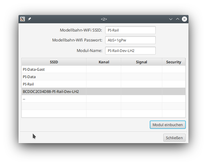
To register, enter the SSID and password of your model railway Wi-Fi, and ideally also a name for the module. Then select the module and click Register Module.
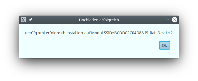
During this process, your PC/tablet/smartphone connects to the CTC module’s configuration Wi-Fi and writes the configuration file netCfg.xml to the CTC module.
As with all configuration changes, the CTC module resets automatically and will then be visible in your model railway Wi-Fi.
Notes:
- Especially on Windows 10, issues may arise when activating the correct Wi-Fi. If the CTC app displays the message “I/O error during upload”, clicking the Register Module button a second time usually helps. If that doesn’t work, you can manually connect to the module’s configuration Wi-Fi via Windows’ Wi-Fi management before clicking Register Module.
- If the PC does not have a wired connection to the model railway network during registration, it will lose its connection to the model railway network. Sometimes, you may need to manually reconnect it to the model railway Wi-Fi afterward.
Logging In via the CTC Module’s Website
Note: This feature is only available starting with firmware version 20210220, which is included with CTC-App v3.05 and pre-installed on all CTC modules shipped after 21.02.2021.
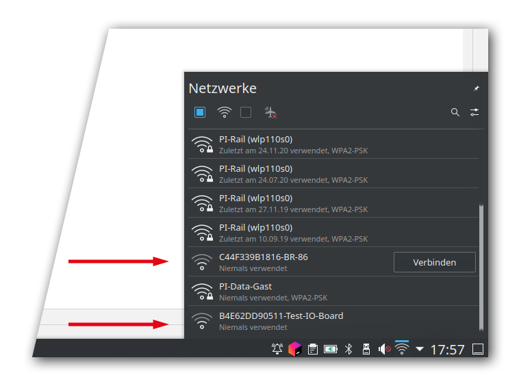
A CTC module in configuration mode will appear in the list of available Wi-Fi networks on your PC, tablet, or smartphone.
You can identify the configuration Wi-Fi networks of your CTC modules by the letter-number combination (MAC address in hex code) at the beginning.
Here is an example from Kubuntu Linux:
- Connect your PC, tablet, or smartphone to this configuration Wi-Fi.
- Open your web browser and enter the address http://192.168.4.1.
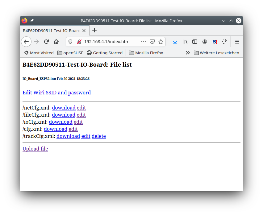
- Click the link “Edit WiFi SSID and password”.
Enter the SSID (Wi-Fi name, network identifier) and password (network key) of your model railway Wi-Fi.
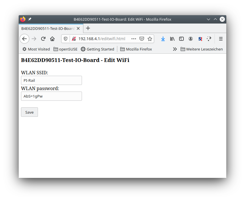
- Click “Save”.
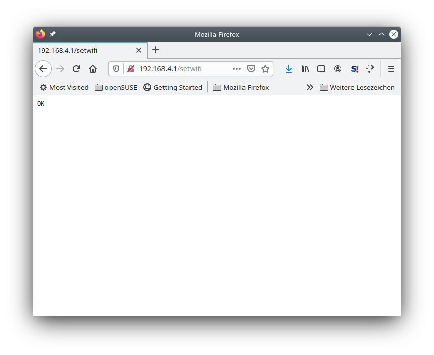
- The CTC module will restart automatically and should now appear in your model railway Wi-Fi.
Note: The module remains in configuration mode for only about 2 minutes before restarting. If the module has a Wi-Fi configuration but cannot connect to that Wi-Fi, it will switch back to configuration mode after about 1 minute. If you mistyped the SSID or password, you must wait one minute before you can access the module again via its configuration Wi-Fi.
Note: You can determine whether the CTC module is in configuration mode by checking the status display of the CTC module.
3.2. Factory New Modules
Factory new switching modules only have the firmware installed, but no configuration set up. Factory new locomotive modules have the motor and headlight preconfigured.
The following steps are necessary to put them into operation:
Log into the model railway Wi-Fi: In the app, look for the menu item Settings/New Modules, call it up and log the CTC module into the Wi-Fi. Your Wi-Fi data (SSID and password) will then be entered in the net.cfg file on the CTC module.
Note: After the upload, the CTC module restarts, i.e., it takes a few seconds until it becomes visible again.
3.3. Status Indicators of the Modules
All modules have a status indicator:
- Yellow LED on CTC-turnout module and CTC Multi-I/O Board
- Front light on locomotives
The start-up process of a CTC module is indicated as follows:
- The indicator lights up until the Wi-Fi is initialized. This happens so quickly that it is not noticeable during a regular start.
- As long as the Wi-Fi is being searched for and until the CTC module has been successfully logged in, the indicator flashes.
- As soon as the CTC module is logged into the Wi-Fi, the indicator goes out.
After a minute of unsuccessful attempt to log the CTC module into the Wi-Fi, the indicator switches to constant illumination. This indicates that the CTC module has set up its own Wi-Fi and is waiting for configuration. See Chapter 3 - Logging Modules into Wi-Fi for more details.
3.4. Wi-Fi Monitor
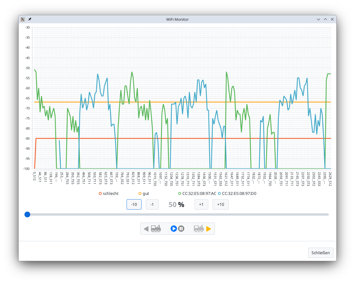
The Wi-Fi Monitor is available starting from CTC-App version 4.15. It displays the Wi-Fi signal reception strength of a locomotive as a graph over time.
You can open the Wi-Fi Monitor via the “Wi-Fi Monitor” button in the locomotive configuration of the respective locomotive.
The example shows the Wi-Fi signal progression during one lap on our garden railway test layout (see article Automation in the Garden):
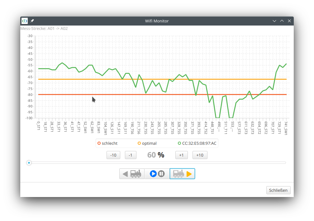
The vertical scale shows the signal strength in dB, while the horizontal scale shows time. The time axis is labeled in tenths of a second (x 0.1 s), followed by the last passed balise. In the example, the locomotive’s reception signal strength was -79 dB after 23.0 seconds (and after balise TS5). Between 44.8 seconds and 55.3 seconds, between balises TS1 and ST3, there were two brief dropouts (-100 dB).
Starting from CTC-App version 4.38, the red line indicates the locomotive’s “Signal min. db” value, i.e., the point at which the locomotive actively begins searching for a better Wi-Fi connection.
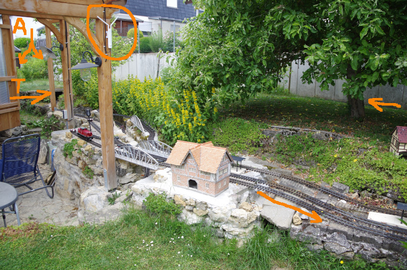
The following image shows the layout where the measurements were taken:
- In the front, the outdoor access point (TP-Link AC1200), to which the locomotive was connected the entire time, is circled.
- In the back, marked with “A,” are the two spots where the Wi-Fi briefly drops out: a slight depression and, before that, currant bushes.
- The arrow labeled “T” points to a tunnel approximately 2 meters long, which obviously does not pose a problem. However, it is only covered with concrete slabs (no soil above) and is open toward the access point.
- The two unlabeled horizontal arrows mark the track layout. The track circles the apple tree, then runs along the concrete wall to the end of the garden, about 15 meters from the access point, and finally returns through the tunnel.
- The test run was conducted with the red BR 251 locomotive visible in the center-left of the image.
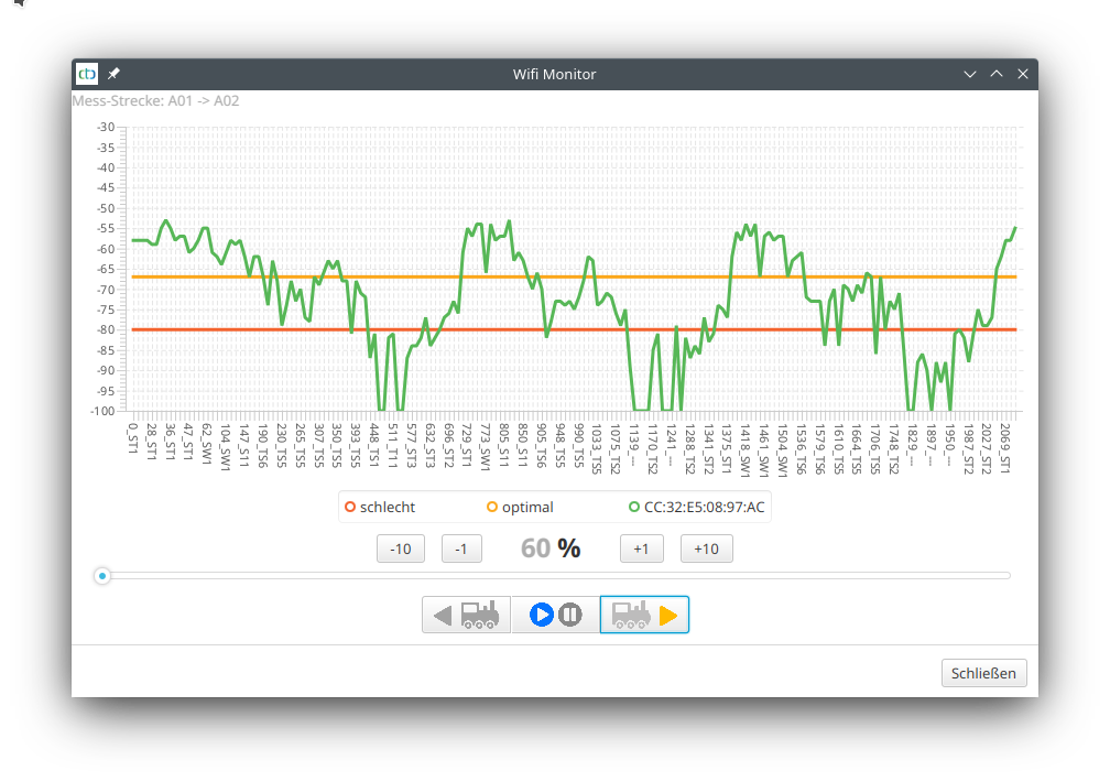
After three laps, the graph looks like this. The three repetitions are also clearly visible in the graph:
Notes:
- For those who want precise details, the data transmitted during the measurement can be found as “Wifi-XXX.csv” in the data folder of the CTC-App (XXX is the name of the locomotive). This file can be opened, for example, with LibreOffice Calc (Excel may work but is not guaranteed) and can be analyzed in detail there.
Mesh Operation
In mesh operation (multiple access points with the same SSID), a separate line is displayed for each access point (here green and blue), making it easy to see when the locomotive has switched access points. The legend shows the MAC addresses of the access points.
Our garden railway test layout has since been expanded, and the access point marked in the photo has been moved four meters to the left to the other support of the terrace roof. This results in larger areas of the layout that are no longer covered by this single access point. The second access point is mounted at the rear corner of the house near the two locations marked with “A” in the photo.
The red line now shows the minDb value of the BR251 locomotive, which was also used here. Three laps were driven on the same track as in the previous example:
The dropouts detected in the first example behind the berry bushes are now optimally covered by the blue access point. However, there is now a critical point between the raspberries (center of the image at the concrete wall, obscured by the apple tree). There, the signal from the blue access point is shielded by the pear tree (behind the lamp in the image), and the signal from the green access point is blocked by the apple tree.
Note:
- For mesh operation, the locomotive should have at least firmware version 20250627 (CTC-App 4.40). In earlier versions, mesh operation was partially available but not yet reliable.
3.5. Statistics
The “Statistics” dialog can be opened via the menu. Here, data is collected (from the start of the CTC App) for all CTC modules:
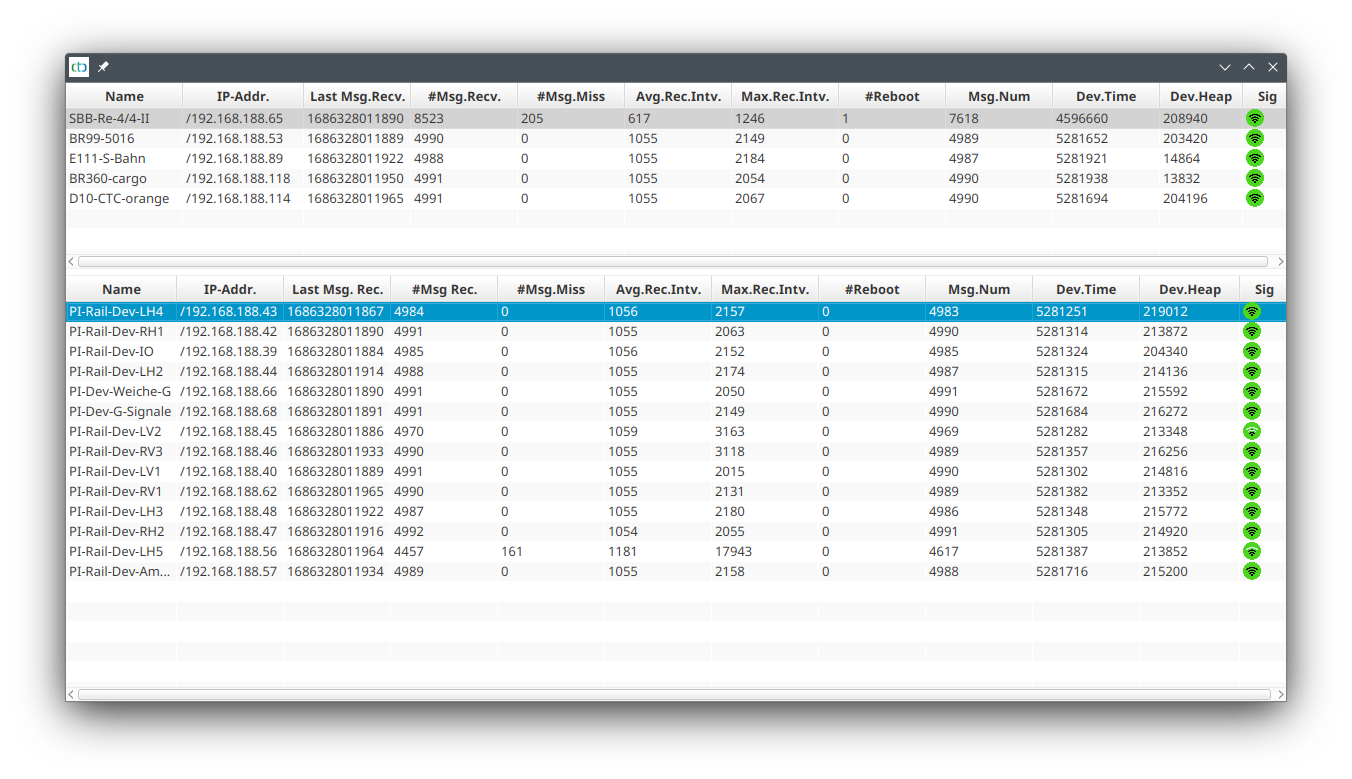
| Column | Meaning |
| Name | Name of the CTC module |
| IP-Addr. | Current IP address of the CTC module |
| Last Msg. Rec. | Timestamp (app) when the last message from the CTC module arrived |
| #Msg Rec. | Number of messages received by the CTC app from the CTC module |
| #Msg.Miss | Number of sync messages that the CTC module did not respond to |
| Avg.Rev.Intv. | Average distance between two replies to the sync message |
| Max.Rec.Intv. | Maximum distance between two replies to the sync message |
| #Reboot | Number of reboots of the CTC module |
| Msg.Num | Running number of the message from the CTC module |
| Dev.Time | System time of the CTC module |
| Dev.Heap | Free heap memory on the CTC module |
| Sig | Wi-Fi reception quality |
A small number at “#Msg.Miss” does not pose a problem. However, if the failures are frequent in individual or even all CTC modules, you should look into optimizing your Wi-Fi. You can find a few tips in Chapter 3 - “WiFi”
4. Configuring Modules
Note: Configuration of CTC modules is currently only partially available on Android and iOS.
The configuration dialogs can be accessed via the pencil icon: ![]()
- in the configurator (list of all modules) on the right side of the row.
- in the locomotive list to the right of the locomotive
- on the control page in the bottom right
- in the turnout list to the right of the turnout
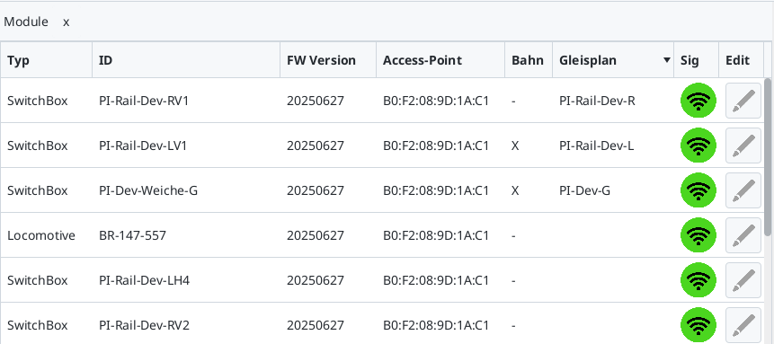
List of All Modules (Configurator)
In this list (menu Settings/Configurator), you will find all CTC modules, including those that could not start properly due to a configuration error:
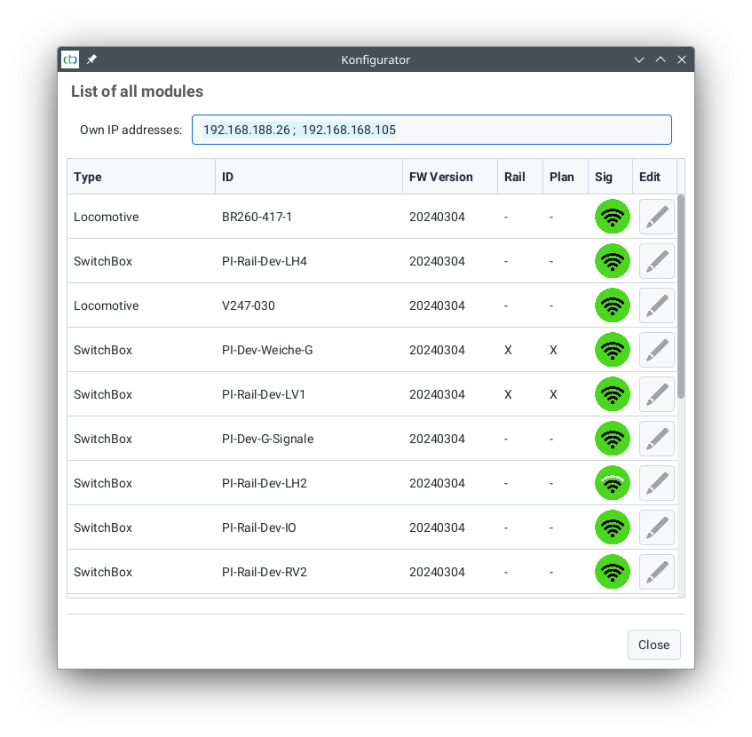
Additionally, you can see here which modules have a track plan and/or a model railway (overall plan) stored for the track diagram control panel (see the crosses in the corresponding columns).
Config Backup
Via the menu item “Settings / Config Backup” in the CTC app (desktop), you can back up the configuration files of all CTC modules currently visible in the CTC app. You select a folder on your hard drive as the backup directory. Then, for each accessible CTC module, a folder named after the CTC module is created in this backup directory, and all configuration files are saved within it.
Locomotive Configuration
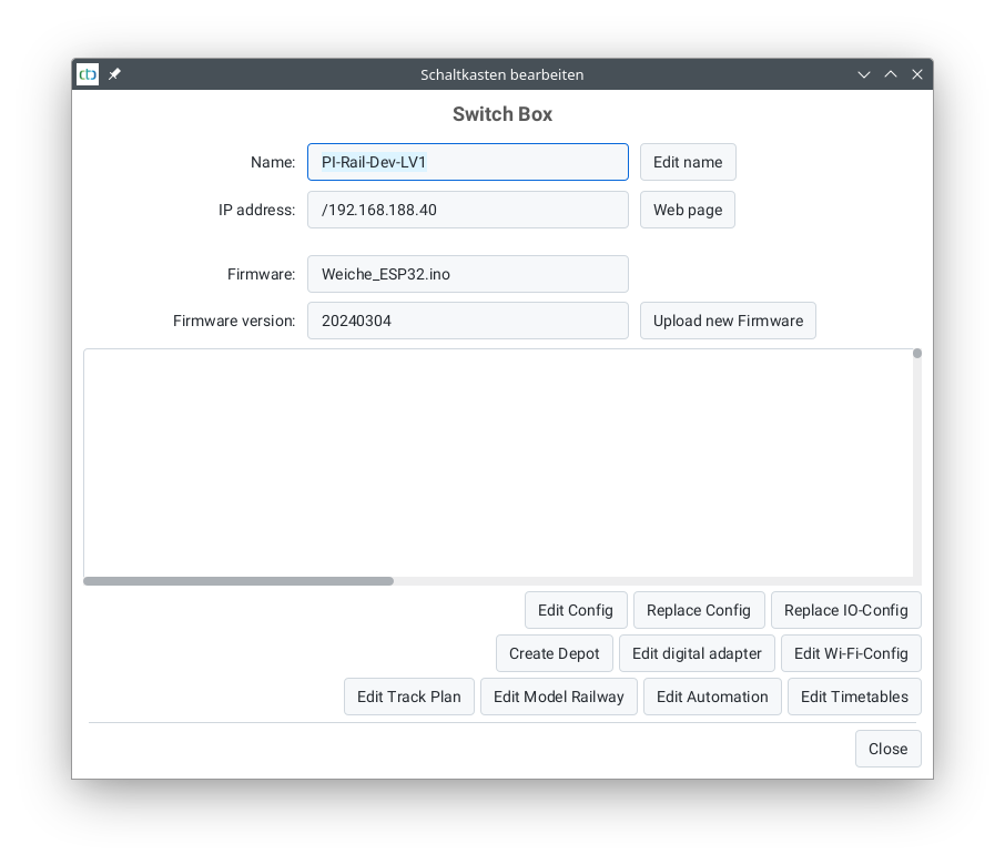
Switchbox Configuration

Unknown Modules (Unknown Device)
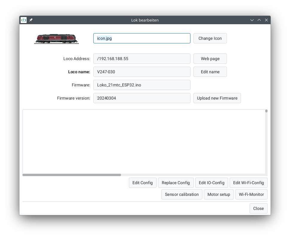
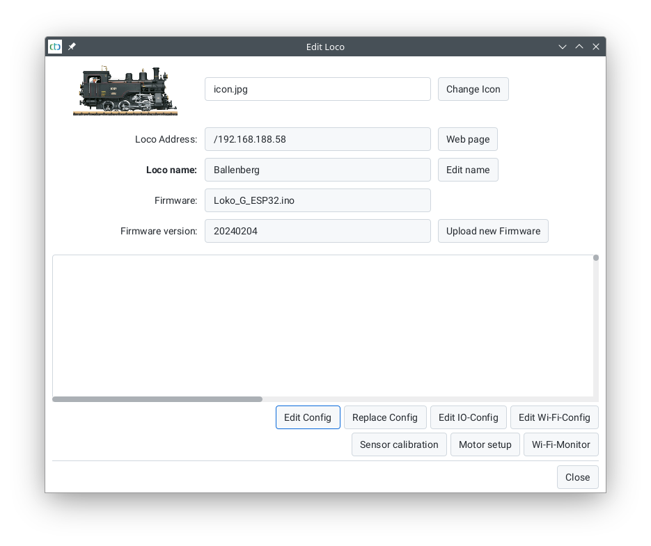
Firmware
The “Firmware” field indicates which firmware (or hardware) this CTC module is using. The “Firmware Version” field shows the release date of the firmware (year, month, day), e.g., 20230829 corresponds to 29 August 2023.
Using the “Upload New Firmware” button, you can update the firmware of this CTC module. First, you will be offered the firmware version included with the CTC app, but you can also select a file from another source. To find out which firmware versions are included with each CTC app release, refer to the Download Section.
Log Output
Below the firmware fields, you will find the Log Output. This section has always displayed the messages from the upload tool when uploading firmware. Starting with CTC-App 4.19 and the corresponding firmware version, all log messages from the CTC module are also displayed here. This makes it significantly easier to identify configuration errors.
As of CTC-App 4.20, the log output is editable. This allows you to select the entire content using the keyboard shortcut “Ctrl-A”, then copy it with “Ctrl-C” to the clipboard. From there, it can be pasted into support request emails.
Modifying the Configuration
The config (cfg.xml) defines which products (turnouts, signals, lamps, etc.) are connected to your CTC module and how they can be controlled—i.e., where and how they are displayed and operated in the CTC app.
The available connections are listed in the I/O config (ioCfg.xml), which is already preinstalled on your CTC module upon delivery.
The following options are available, each explained in detail in the respective chapters:
- Product Catalog: Introduced with CTC Version 3, this concept simplifies configuration to just a few easy-to-understand steps.
- Linking Actions: Based on the actions automatically created via the product catalog, you can link them—for example, to make a locomotive automatically stop before a red signal.
- Creating Custom Actions: If you need actions not included in the product catalog, you can add your own.
- Connecting and Configuring DCC Decoders: Unfortunately, this involves the full complexity of DCC, which is why it has its own dedicated chapter.
- Creating a Custom Product Catalog (Appendix): Standard products are our responsibility, but there will certainly be specialized products missing from our catalog.
Replace Config
With this button, you can reset your CTC module’s configuration to its factory default state or load an alternative base configuration.
Notes:
- Please note that this refers to the configuration version included with the CTC app. Before replacing the configuration, you should therefore update your CTC module’s firmware.
- Up to CTC app version 4.18, this button was labeled “Delete Config”.
Replacing IO-Config
From CTC-App version 4.19, it is possible to replace the ioCfg.xml of the CTC module with a newer or alternative version.
Previously, this was only possible via the module’s HTML page.
Notes:
- Please be aware that this refers to the configuration version included with the CTC app. Before replacing the configuration, you should therefore update the firmware of your CTC module.
- The method via the module’s HTML page is still available today but should be avoided, as no plausibility checks are performed when using this method.
Changing the Digital Adapter
Using “Change Digital Adapter”, you can configure CTC to control locomotives and turnouts connected to a digital command station. For more details, see Chapter 8.2 – “Legacy Digital: Integrating a Z21 Command Station”.
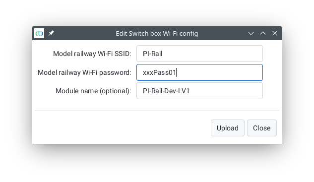
Change Wi-Fi Configuration
This dialog allows you to modify the Wi-Fi configuration (netCfg.xml) of a currently registered CTC module. For example, you can reconfigure a locomotive on your home layout for your model railway club’s Wi-Fi before leaving the house.
WARNING: After uploading, the CTC module will automatically reset and will only be visible in the newly configured model railway Wi-Fi network.
If something goes wrong during this process, you can reconnect the CTC module to your model railway Wi-Fi as described in Chapter 3.1 – Registering Modules in Wi-Fi.
Basics about Wi-Fi and the “Signal min. db” (Mesh) parameter can be found in Chapter 3 – Wi-Fi.
Track Plan and Model Railway Modifications
Use these two buttons to access the configuration of the CTC app’s track diagram control panel. They are described in Chapter 6 – Track Diagram Control Panel.
Modify Automation
Use this button to access the configuration of actions related to automatic operation that cannot be directly assigned to a CTC module. These include:
- Triggers for NFC balises
- Blocks (track sections) and actions for setting routes between blocks
- Train orders
They are described in Chapter 7 – Automation.
Changing Timetables
With this button, you can modify timetables. How to do this is described in Chapter 7.4 - Timetables.
4.1. Config - Connect Products
The simplest way to get CTC modules up and running is via the “Connect Product” function.
You can access this through the “Change Config” button in the locomotive or switchboard configuration (see previous page).
The configuration shown here is stored on the CTC module in two files:
-
In the Config (cfg.xml), the functions controllable via the app such as lights, uncouplers, switches, signals, etc., are defined.
-
In the IO Config (ioCfg.xml), the input & output pins and interfaces configured for the CTC module are defined.
Since these describe parts that are permanently installed on the CTC module, they cannot be changed via the dialog in the app.
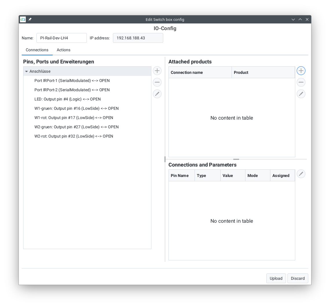
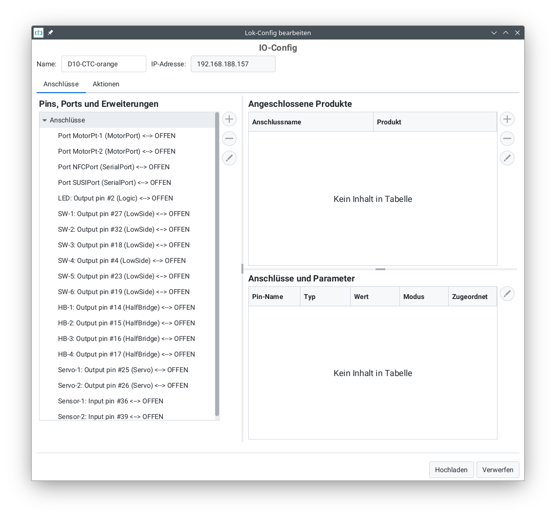
The content of the IO Config is displayed under the heading “CTC Module: Pins, Ports, Chips”.
All other displayed data comes from the Config.
Adding a Product
To add a product, click on the plus symbol to the right of the “Connected Products” table. A list of product catalogs included with the CTC-App will open.
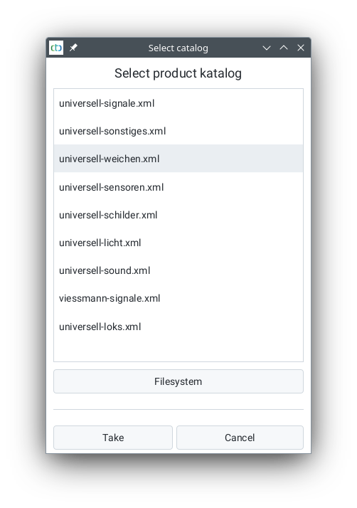
You can select one of the included catalogs or load a product catalog from the file system by clicking on the “Select from File System” button. Here, the included catalog “universell-weichen.xml” was selected and then “Apply” was clicked:
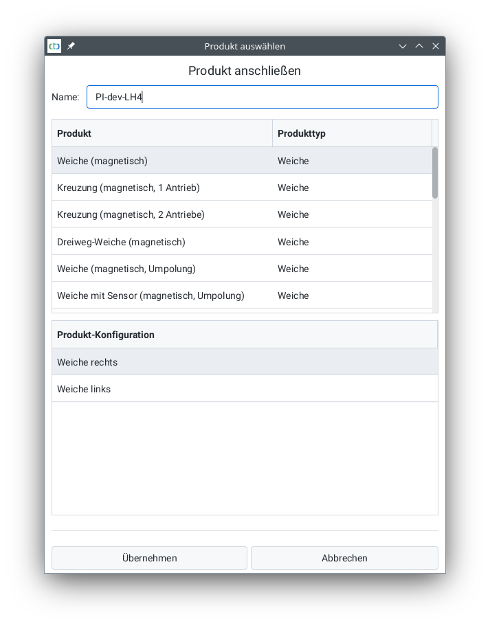
Now select the appropriate product. For some products, you can also choose from different configurations.
Then, enter a name for the connected product and click on “Apply”.
Now you only need to specify which connections of the product are connected to which pins or ports of the CTC module:
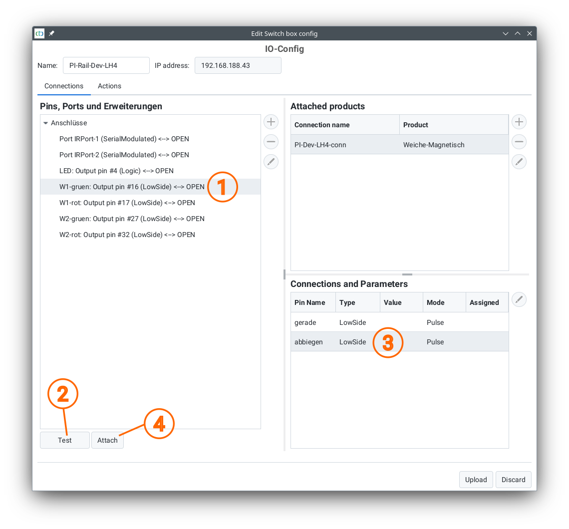
- The newly added product must be selected in the “Connected Products” table. Then select the corresponding port of the CTC module in the “Pins, Port, and Extensions” table.
- With the “Test” button, you can check which pin of the connected product is attached to the selected port of the CTC module.
- Then select the pin determined by the test in the “Connections and Parameters” table.
- By clicking the “Connect” button, the product’s pin is logically connected to the port of the CTC module.
Now you can see the established connection in the two tables “Pins, Port, and Extensions” and “Connections and Parameters”:
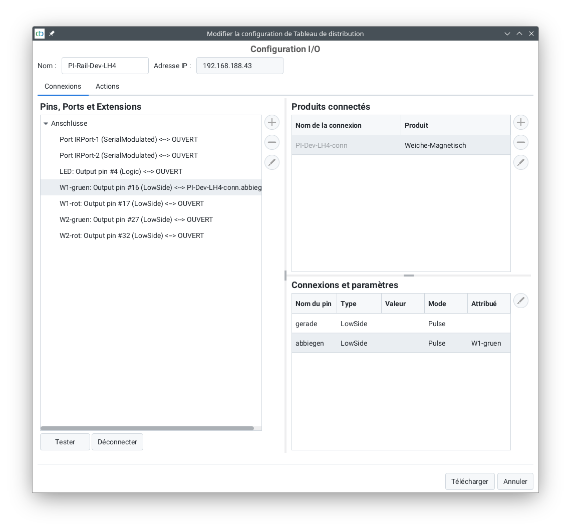
Repeat the above four steps until all connections of the product are linked.
WARNING: The CTC-App ensures that the connections of the product can only be linked with matching pins or ports. However, if you have selected an incorrect product, this can indeed lead to damage to the CTC module and/or the product. Particularly noteworthy here are the electromagnetic drives, as used, for example, in Märklin turnouts (whose end switches do not function). If these are connected not as pulses but as switches, they will be destroyed after a few seconds.
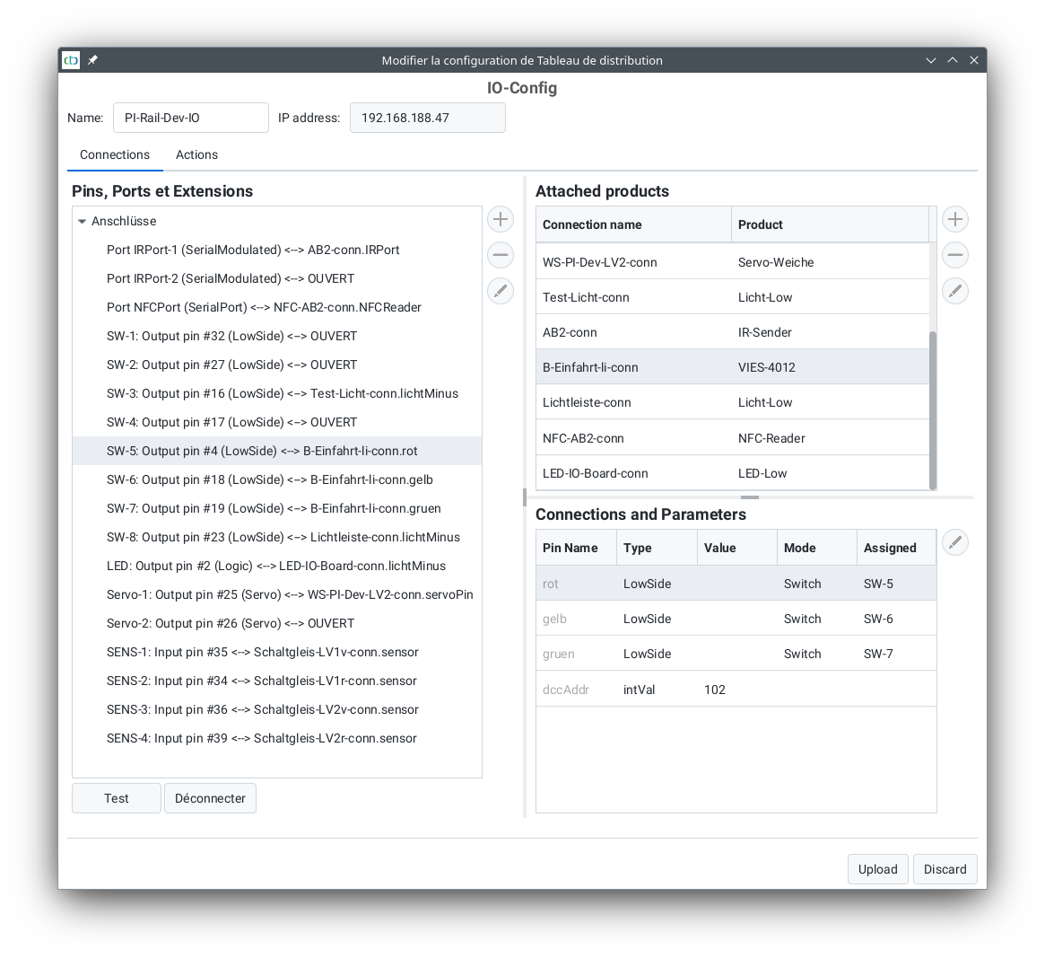
Example Configuration of a CTC Multi I/O Board
This is what the configuration of the CTC Multi I/O Board of our demo system looks like:
4.2. Config - Actions
Actions are at the heart of CTC’s control functions. They determine both which buttons and sliders appear where in the CTC app, and what should happen automatically.
Note: If you have connected a product, as described in the previous chapter, matching actions have already been created. However, some of these need to be finished configuring, e.g. an IR balise already has a trigger for linking with a signal, but the signal still needs to be chosen as the “trigger”.
There are the following types of actions:
- Function: Appears as buttons in the CTC app, e.g. to control turnouts and signals or to activate locomotive functions.
- Value slider: Appears as plus/minus buttons and sliders in the CTC app to adjust a numerical value.
- Trigger: This allows the CTC app or the CTC module to respond to the change of any other action, e.g. a signal can turn red after a turnout has been activated.
- Sensor: This action is connected in the CTC module with a sensor, e.g. a contact track. The value of the sensor is displayed in the CTC app and can (like all actions) trigger a trigger.
- Timer: This action serves to do things regularly or after a certain time, e.g. our IR balise is a timer that cyclically sends an infrared message.
Each action has a state in the form of a letter or a number. This state can be used in the trigger to react to specific state changes.
By the way, when you add a product, matching actions are also created straight away.
Note: Actions that cannot be assigned to a CTC module are edited via the “Change Automation” button. These are for example the triggers of an NFC balise.
Function
A function is a collection of related buttons or switches. Each of these buttons is associated with a script (see Chapter 4.5 - Editing Scripts) that is executed when the button is pressed.
For example, a turnout has two buttons, one for “straight ahead” and one for “turn”. Pressing the button triggers the corresponding CTC module to execute the associated script. In the case of our turnout, for example, a 250ms long pulse is given to the turnout drive, thus setting the turnout.
The function always reports its last triggered button as the state. This then provides the basis for triggering subsequent actions using a trigger.
In contrast to most model railway controls, our function may also consist of more than two buttons.
Value Controller
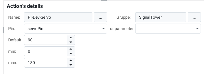
With a value controller, a numerical value can be adjusted, for example, a servo can be set to a specific angle. The most obvious value controller is the speed controller of a locomotive.
The status of a value controller is the last set value.
Trigger
A Trigger is very similar to a function, but it is not triggered by a button, but by the state change of another action.
Like the function, the trigger consists of multiple scripts (refer to Chapter 4.5 - Edit script) which are executed depending on the new state of the triggering action.
If the trigger is stored on the same CTC module as the triggering action, then this trigger is initiated directly by the CTC module. Otherwise, the CTC-App takes care of triggering it.
Timer
A timer can either be executed regularly (cyclically) or only once.
After its time has elapsed, the timer executes its script (see Chapter 4.5 - Editing script). This way, you can, for example, control motorized turnouts by turning on the motor in the script of a function and calling a timer that then turns off the motor after a predetermined time (e.g. 5 seconds).
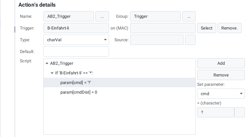
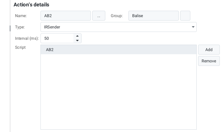
The IR sender is a special case: It has no script and (hard-coded) regularly sends a message via infrared. The message is composed of the name of the IR transmitter and the predefined parameters dist, cmd and cmdDist. Here we recommend adding the product “IR-balise” from the product catalog “universal-sensors.xml”.
Sensor
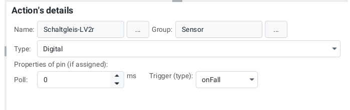
A sensor is linked to an input pin of the CTC module (currently only Multi-I/O-Board). The sensor then passes on the state of the input pin as its state.
With the help of a trigger, a follow-up action can now be started.
4.3. Config - Linking Actions
A trigger can be linked with another action to respond to a state change of this action.
Apart from the examples mentioned below, you will find an ever increasing number of instructions in “Appendix B: Examples”. You will receive a very detailed step-by-step guide in the separate document “CTC-Starter-Sets”.
Linking IR-Balise (IR-Transmitter) with Signal
The simplest form of linking is triggering an IR balise. It’s already created while selecting the IR balise from the product catalogue “universal-sensors.xml”. You just need to specify which signal it should respond to and enter the distance to the signal.
Select the trigger of the IR balise (here AB3-Trigger):
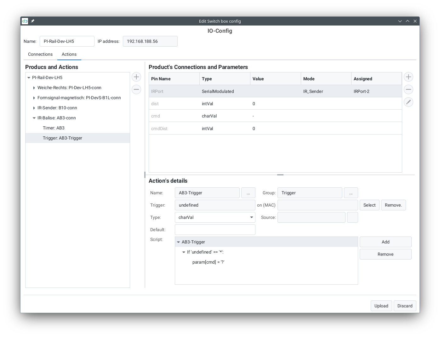
Then click on “Select” to the right of the trigger. The following dialogue box will open:
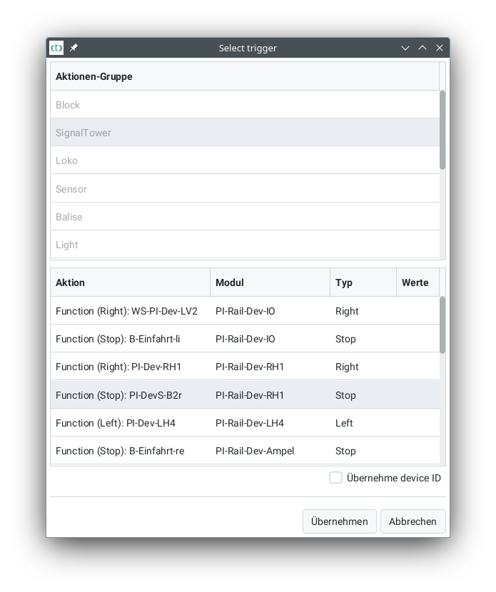
Choose the signal to link (usually in the “SignalTower” group) or sign, and then click on apply.
The name of the selected signal will now be displayed under “Trigger”. A star should appear in the “on (MAC)” field.
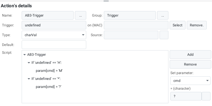
In the simplest case, the pre-made script should be left unchanged. It takes over the distance (cmdDist) from the parameters and the value of the signal as a command.
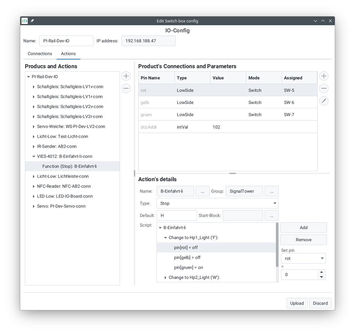
In the following example, for the ‘H’ (stop) state of the signal, the ‘M’ command is sent out. In all other cases (‘*’), the state of the signal is taken as the command (‘?’). Also, the distance (in cm) between the IR balise and the point from where the command should apply is specified.
Linking NFC Balise with Actions
To be able to link an NFC balise with actions, a balise must be created. Since an NFC balise is not connected to a CTC module, the balise is stored in the track diagram. You can find out how to do this in the chapter “Balises (ID Transmitters) in the Track Plan”
Once the balise is created, the already established trigger for the NFC balise can be edited via the “Change automation” button, similar to the IR balise:
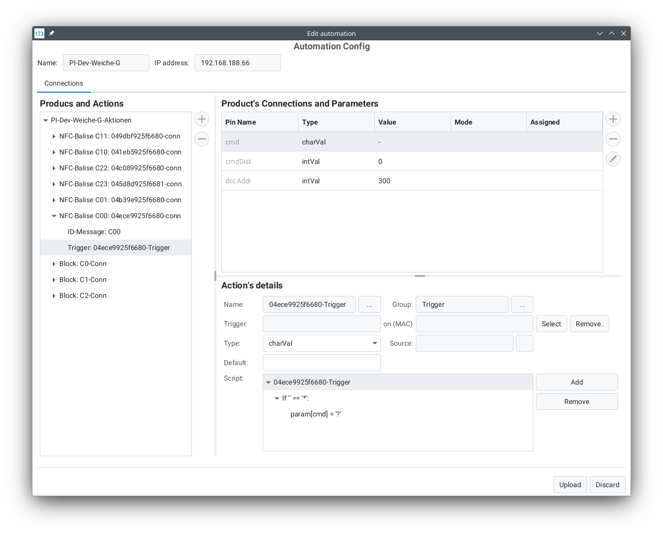
Then click on “Select” to the right of the trigger. The following dialog will open:
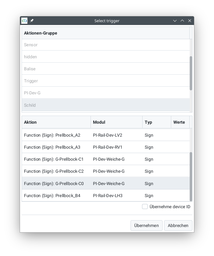
Select the signal or sign to be linked (here a sign) and then click on apply.
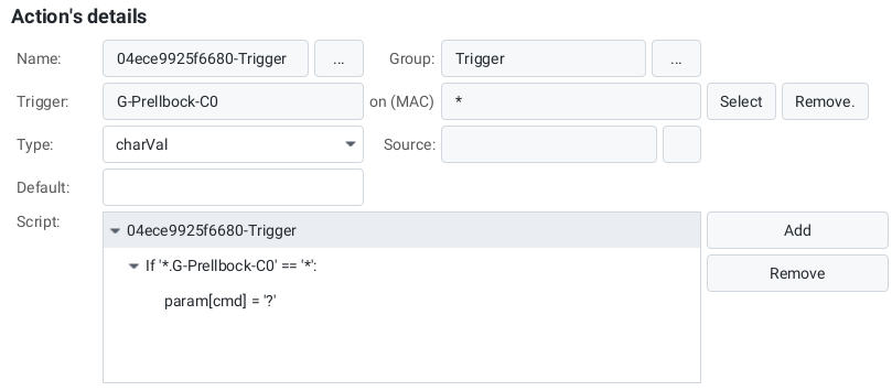
The name of the selected sign is now displayed at “Trigger”. In the field “on (MAC)” a star should be displayed.
In the simplest case, leave the pre-made script unchanged. It takes the distance (cmdDist) from the parameters and uses the value of the sign as the command.
Note: If the trigger for a trigger is located on the same CTC module as the trigger itself, the CTC module itself deals with executing the trigger. Otherwise, the CTC app takes care of triggering the corresponding trigger.
The editing of scripts is dedicated to its own chapter.
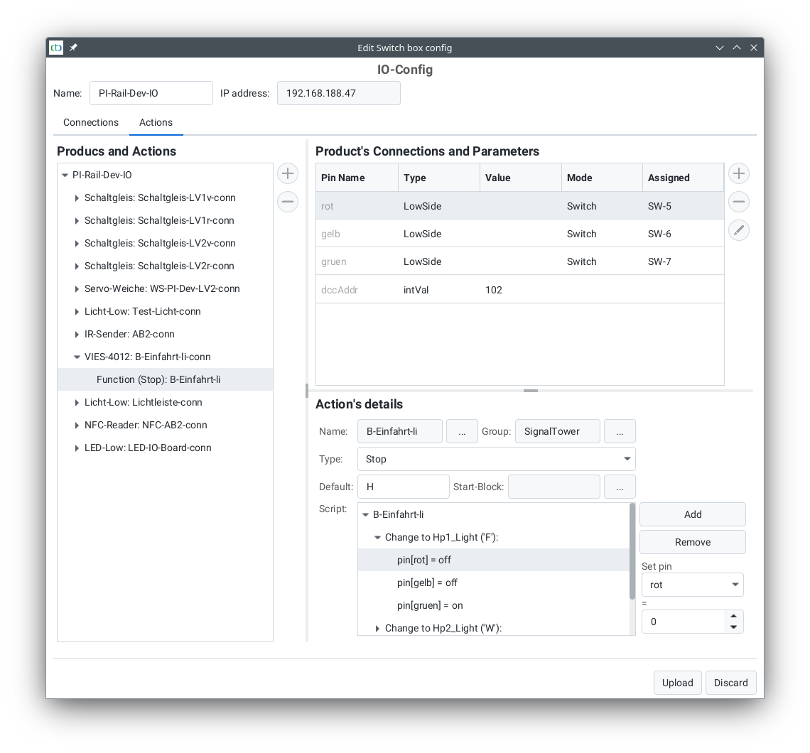
4.4. Config - Editing Actions
On the “Actions” tab of the Config dialog, you can edit, delete, and add actions:
4.5. Config - Editing Scripts
Scripts exist in functions, triggers, and timers. They define a sequence of simple commands that are executed when the action reaches a specific state.
Scripts consist of the following simple commands:
pin[]: Set an output pin to a specific value.param[]: Set a parameter to a specific value.pause(): Wait for a specified number of milliseconds.call(): Call another action on the same CTC module, e.g., a timer.wenn (): Execute the commands under “wenn” only if a parameter has a specific value.
In the script for a driving order, there is an additional command:
on XXX: The locomotive should pass balise XXX and optionally execute a command—see Chapter 7.3 - Driving Orders
Note:
- The commands
callandifcreate nesting. If a script’s nesting exceeds 10 levels, it will terminate with an error starting from CTC-App 4.40 and firmware 20250627. - From CTC-App 4.40 onward, script execution and state changes are logged in the file “Action-Log.csv”. This file is located in the CTC-App’s data folder and is recreated (overwriting old content) each time the CTC-App starts. It can be conveniently viewed with LibreOffice Calc (Excel may work but is not guaranteed).
When an action’s state changes depends on the type of action:
- Functions and value controllers are changed by the user in the CTC-App by pressing a button or adjusting a slider.
- Timers are triggered automatically by the CTC module either once after a set time or at regular intervals.
- Sensors are triggered via switches. These can be pressed manually or activated by a passing locomotive or wagon.
- Triggers are activated as a result of another action. Triggers can be functions, value controllers, sensors, or IDs read by locomotives.
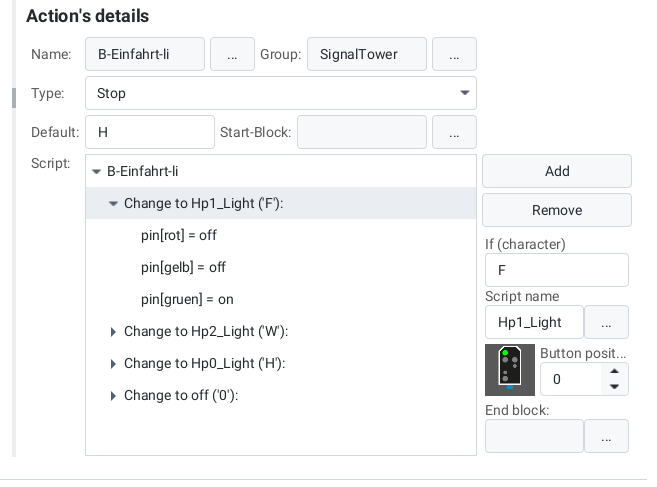
The top level of the script defines how the action should respond to specific values.
In the value configuration, the actions possible for a function are defined (they are part of the cfg.xml).
For example, for a locomotive’s light, the following four actions can be defined:
- off
- on
- front
- back
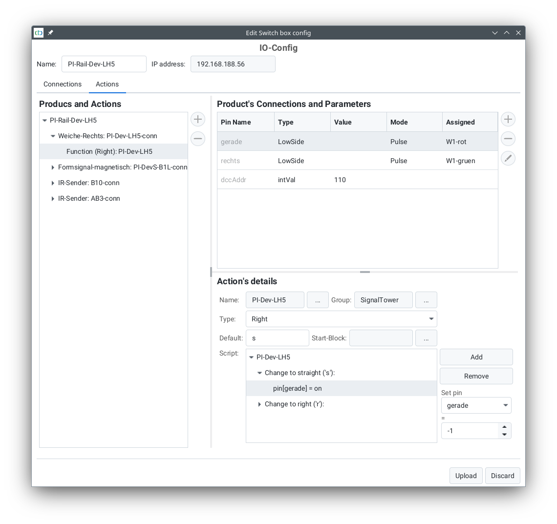
For each action, you can specify which of the outputs defined in the IO configuration should be switched. This is often just a single output, but it can also be a conditional sequence, as shown in the example dialog for the straight action of the turnout PI-Dev-LH5.
For turnouts, note that the icon displayed in the turnout list is determined by the action name. The position (0 to 2) indicates the column in the turnout view:
| Function | Action Name | Symbol | Icon | Recommended Position |
| Left turnout | left_left | l |  |
0 |
| left_straight | s |  |
1 | |
| Right turnout | right_straight | s |  |
1 |
| right_right | r |  |
2 | |
| Three-way turnout | three_left | l |  |
0 |
| three_straight | s |  |
1 | |
| three_right | r |  |
2 | |
| Crossing turnout | cross_notcross | x |  |
0 |
| cross_cross | n |  |
1 | |
| 4-way crossing turnout | cross_hor | h |  |
0 |
| cross_vert | v |  |
1 | |
| cross_left | l |  |
2 | |
| cross_right | r |  |
3 |
Commands for Locomotives / Signals
The following commands can be interpreted by locomotives when linked to a balise:
| Function | Symbol | Meaning | cmdDist | Description |
| Stop (Hp0 / red) | ‘H’, ‘h’ | Indicates an upcoming red signal. | Distance | The locomotive brakes and stops before this signal. If the signal turns green again, the locomotive resumes travel and accelerates to the maximum speed permitted by the signal. |
| Proceed (Hp1 / green) | ‘F’, ‘f’ | Indicates a green signal. | Distance | Any previous speed restriction is lifted. In manual control, nothing happens; otherwise, the locomotive accelerates to its maximum speed. |
| Slow Speed (Hp2 / green+yellow) | ‘W’, ‘w’ | Indicates slow-speed operation. | Distance | If the locomotive is too fast, it brakes to a reduced speed (e.g., to prevent derailment over a diverging turnout). |
| Speed Restriction | ‘L’, ‘l’ | Indicates a speed restriction. | Speed | If the locomotive is too fast, it brakes to this speed. The distance value is multiplied by 10 and interpreted as speed (e.g., “50” = 50 cm/s). |
| Minimum Speed | ‘M’, ‘m’ | Indicates an upcoming red signal with a second balise for the final stop. | Distance | The locomotive slows to a crawling speed. The second balise before the signal then sends a “Stop” command with a distance of 0 cm or an emergency stop. |
| Emergency Stop | ‘E’, ‘e’ | Emergency stop (e.g., just before track end or signal). | Distance | The locomotive stops abruptly. If the signal turns green again, it resumes travel and accelerates to the maximum speed permitted by the signal. |
| Stop | ‘S’, ‘s’ | Indicates an upcoming scheduled stop. | Pause (seconds) | In automatic mode, the locomotive stops, waits for the pause duration, and then continues. From CTC-App 4.08: In manual mode, behaves like a protective stop with distance 0. |
| Return Trip | ‘R’, ‘r’ | Indicates an upcoming stop at a timetable reversal point (e.g., shuttle train). | Pause (seconds) | In automatic mode, the locomotive stops, waits for the pause duration, and then continues in the opposite direction. From CTC-App 4.08: In manual mode, behaves like a protective stop with distance 0. |
| Protective Stop (Sh2) | ‘T’, ‘t’ | Indicates the end of track (e.g., buffer stop). | Distance | The locomotive brakes and stops before this marker. |
Almost every command is associated with a distance in cm, determining where the command takes effect. The locomotive calculates its braking distance accordingly—for example, a “Stop” command with a distance of “65” ensures the locomotive comes to a halt after 65 cm.
Note: A properly calibrated motor sensor is required for functional target braking (see Chapter “Calibrating the Motor Sensor”).
Commands can either be permanently assigned to a balise or dynamically modified using “triggers.” For example, a balise can be linked to a signal’s state (see Chapter “Config – Linking Actions”). For this reason, the same letters should be used for signal states as for the corresponding locomotive command.
4.6. Config - Connect DCC decoder
IMPORTANT: Everything described here requires at least CTC-App Version 3.10 and Firmware 20200514!
Basic Functionality: Motor and Headlights
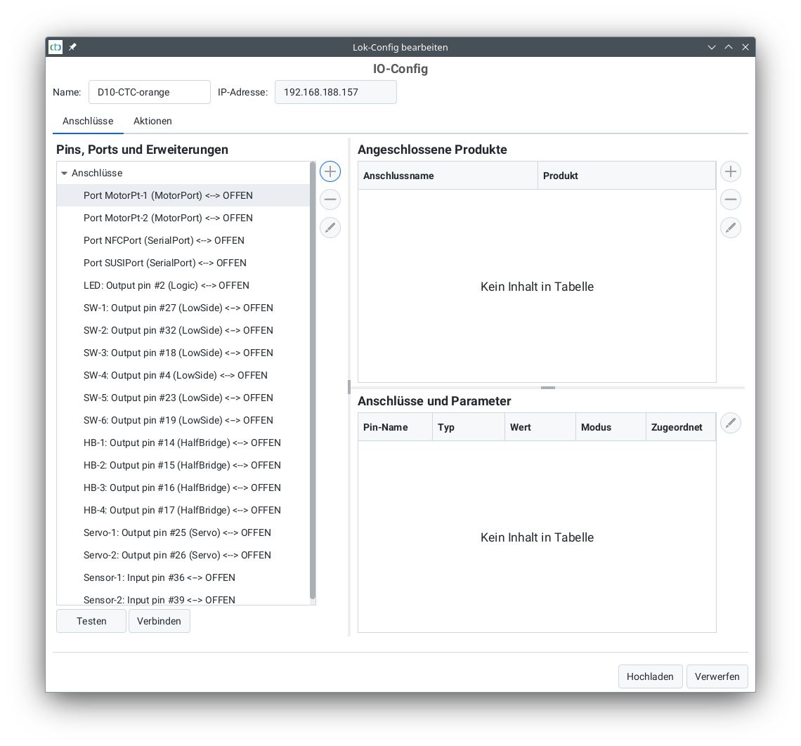
Since the CTC locomotive modules are preconfigured for direct connection of motor and lights, these must first be removed from the configuration. To do this, open the module configuration in the CTC-App (see User Manual Chapter 4).
Click on the “Change Config” button to inform the CTC module about the functions of your digital decoder.
Remove all connected products there by selecting each line in the “Connected Products” list and then clicking the minus button to the right. After that, the dialog appears as follows:
Then select the motor port to which you have connected the digital decoder:
After clicking the plus button next to it, the following dialog opens:
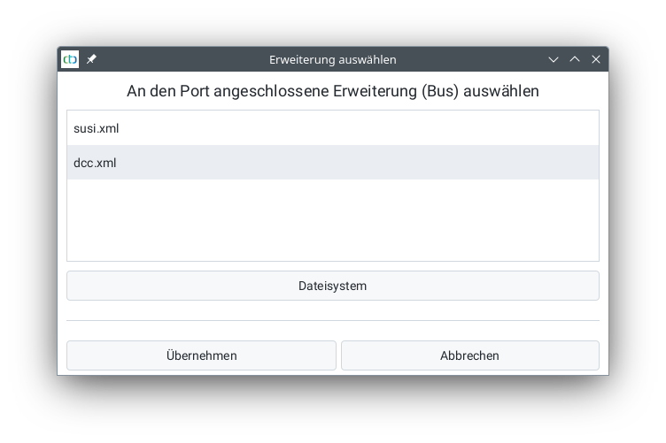
Select “DCC.xml” and click “Apply”. In the following dialog, assign a name for the extension (here “DCC”), enter the DCC address (for new locomotives this is 3), and select “DCC Locomotive” in the table:
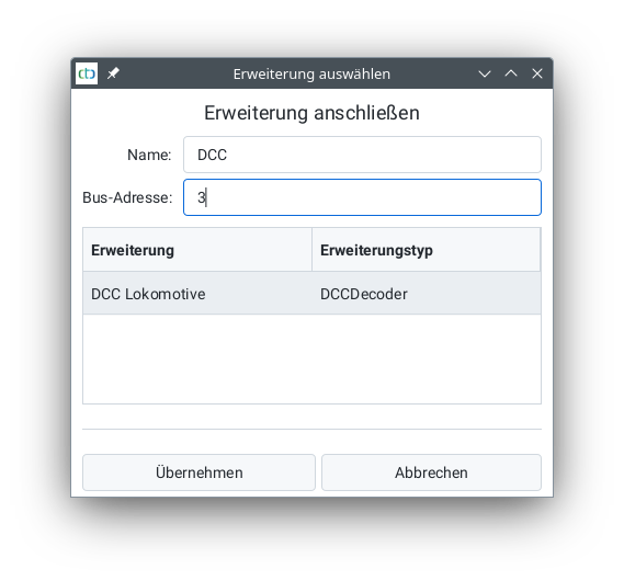
After clicking “Apply”, you can expand the motor port and see your added extension:
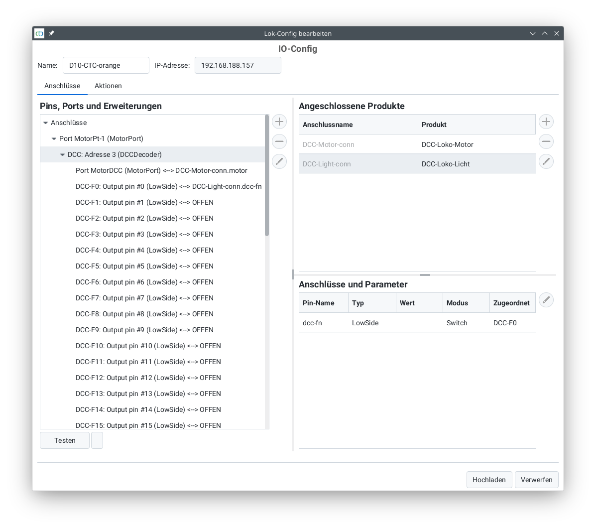
Now it’s worthwhile to press the “Upload” button for the first time, because only then can you try out the functions of the digital decoder using the test button. The motor and headlights are already correctly wired, meaning you can now switch to locomotive control and attempt a first test.
Configuring Sound
After completing the basic configuration, you can take care of the sound functions.
To do this, click again on “Change Config” and expand the motor port to which you have connected your digital decoder:
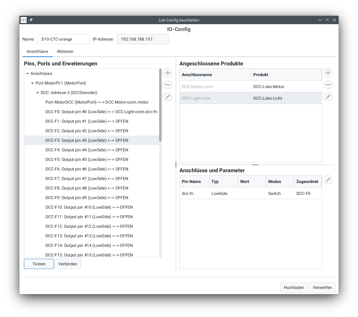
To check what is behind each function, select the function (in the image “DCC-F3”) and press “Test”.
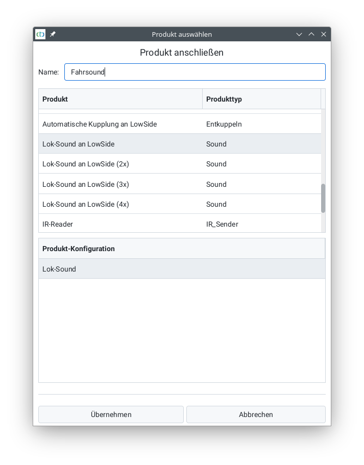
If you want to make this function available in the locomotive control, then press the plus button next to “connected products”. Select the catalog “universell-loks.xml” and then “Locomotive Sound to LowSide” for sound or “Locomotive Light to LowSide” for light functions:
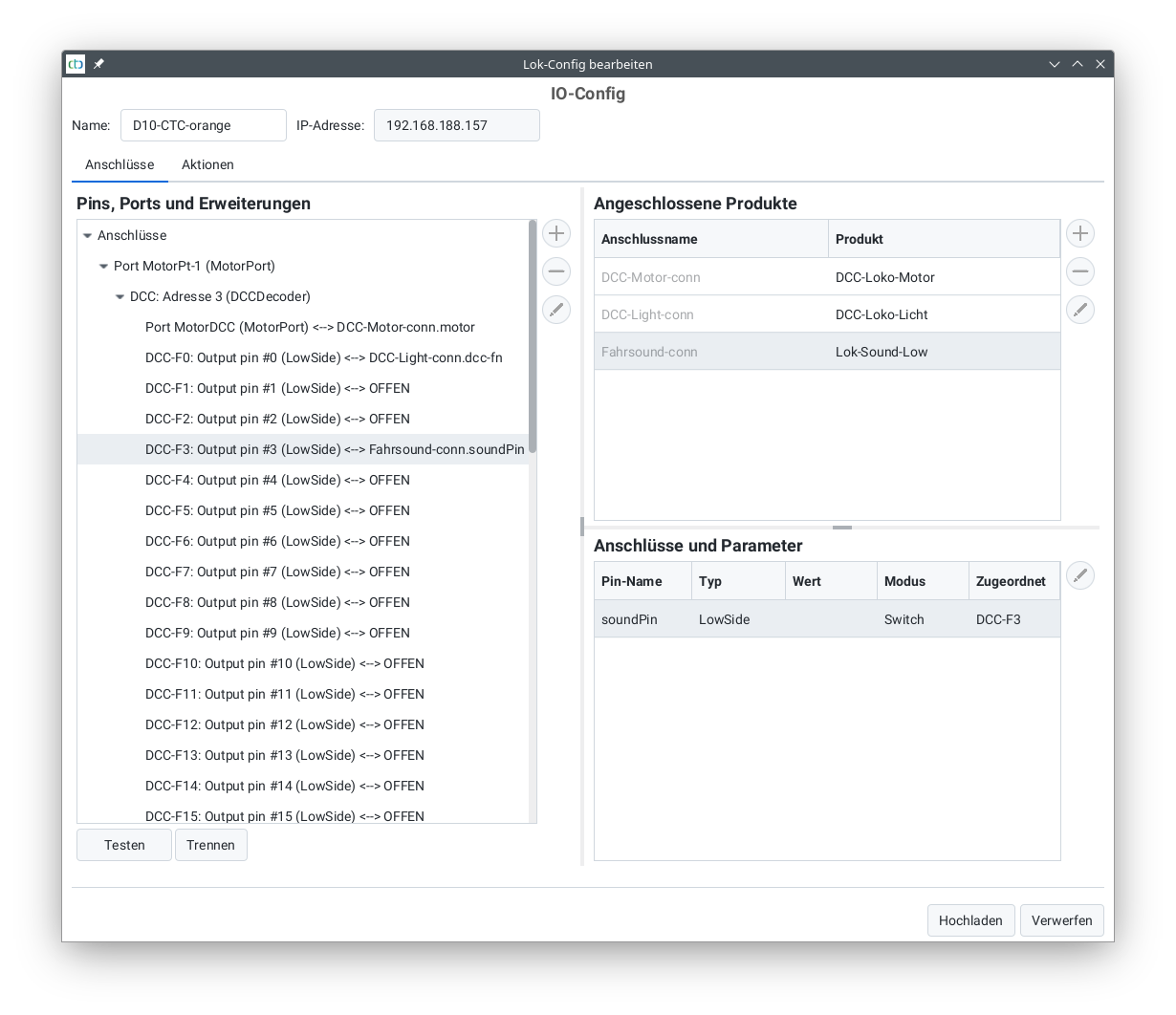
Then, at the bottom right, select the “soundPin” and click on the “Connect” button:
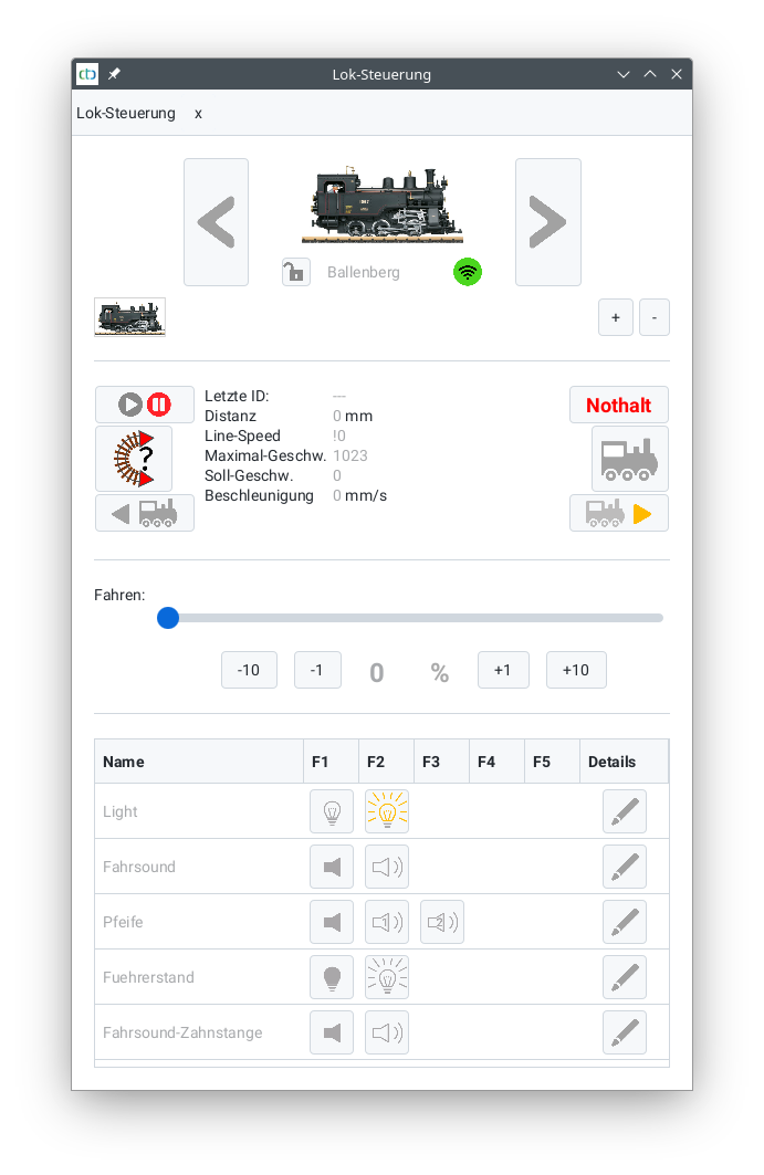
After all desired DCC functions are configured, the locomotive control looks like this:
5. Configure the engine
Programming the CTC locomotive modules reduces the configuration effort to a few steps.
If you only want to drive manually and without load regulation, and also do not want to use either train protection or automation, there is nothing else you need to do. In our experience, the pure motor control of the CTC module is compatible with all common direct and alternating current motors. From the ancient 3-pole motor, the high-performance 5-pole drive, to current motors with a flywheel, everything has worked with the CTC module straight away.
The Calibration of the motor sensor is necessary for the following functionalities:
- Spot-on target braking before, for example, a red signal
- Load regulation, that is, the locomotive drives at the same speed uphill and downhill
The step Adjusting the engine allows optimizing the control parameters of the load regulation and target braking.
5.1. Motor-Sensor Calibration
For precise target braking in front of a red signal or even for load regulation, the CTC locomotive module needs to know how fast the locomotive is actually moving. For this purpose, a sensor is installed in the motor driver of the locomotive, which provides a rough indication of the motor’s speed based on current flow. The calibration process determines a characteristic curve that maps the sensor values to speed.
For a calibration to be carried out, a measuring track consisting of two balises must be present. During the calibration, the locomotive autonomously drives over the balises in a circuit or shuttles back and forth.
Note: This process is detailed within the context of the Starter Set, see Starter Set Sensor Calibration
Define Measurement Track
The measurement track is defined in the “Edit Model Railway” dialog:
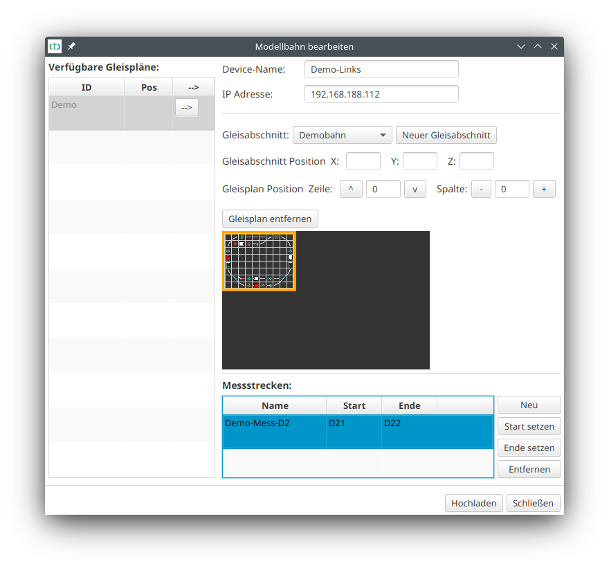
The two balises must belong to the same block (first two characters identical) and must come directly after each other. The “distance to predecessor” of the balise with the higher number then determines the length of the measurement track.
Calibrate Motor-Sensor
Open the dialogue “Calibrate Motor-Sensor” via the button “Calibrate Sensor” in the Locomotive Configuration of the respective locomotive.
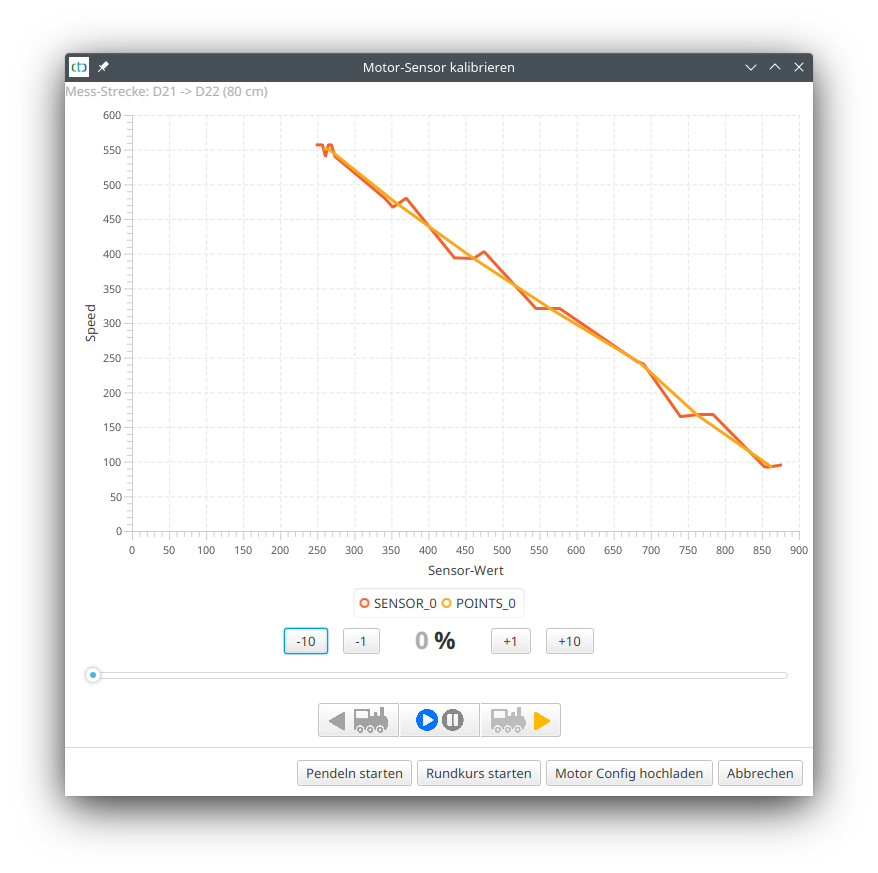
At the top, the measurement track is displayed. Check again if the balise designations and distance are correct.
Accelerate the locomotive to the minimum speed at which it still runs well. Then start the calibration process by clicking on “Start Pendulum” or “Start Circuit”.
Note: When pendulum swinging, the locomotive needs considerable space at both ends of the measuring track.
The locomotive drives the measuring track three times, then accelerates by 10% and drives the measuring track three times again. This repeats until the locomotive has exceeded 80%, then it stops.
The dialog then looks like this, for example, as in the picture above for the Piko BR 147. If you are satisfied with the result, click on “Upload Motor Config”.
Note: Those who want to know exactly will find the data transmitted during the measurement as “Motor-Setup.csv” in their user directory. This can be opened, for example, with Excel or LibreOffice and can be evaluated in detail there.
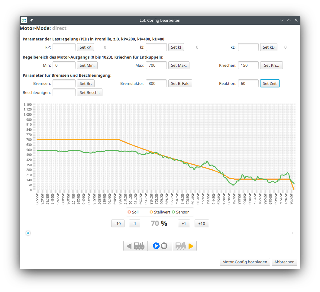
5.2. Adjusting the Motor
Setting the Motor
In this dialog, you can optimize the parameters of the motor control of a CTC locomotive module using live data. The locomotive continuously transmits the value of the motor sensor, the target value and the control value calculated by the PID controller. As long as all three values are 0, the diagram is “frozen”.
The displayed parameters belong to the currently selected operating mode (Motor Mode) of the locomotive. The parameters kP, KI and kD are only relevant in the “PID” motor mode and are ignored in “direct” motor mode.
When you click on the respective set button, the value to the left of it is directly transferred to the locomotive and remains there until the locomotive is reset. It is only when you click on “Upload Motor Config” that your settings are permanently saved.
Parameters of load regulation (PID controller):
- kP determines how directly the motor reacts to changes to the sensor. A value that is too high leads to jerky driving behavior, a value that is too low means that it takes a very long time for the motor to react to a changed target or sensor value.
- kI determines how strongly the motor reacts to the sum of all target value deviations.
- kD determines how strongly the motor reacts to the difference between the current and previous sensor.
- The sample rate can only be set directly in the cfg.xml and should remain at the default of 20 ms.
Control range of the motor output:
- Min and Max define the regulation range of the motor (0..1023). This allows you to exclude the lower range in which the motor does not rotate and limit the maximum speed.
- With Crawl you set the crawling speed, which is driven when uncoupling (“coupling waltz”) as well as the target speed for decelerating to minimum speed.
Parameters for braking and acceleration:
- Brakes is the acceleration constant for braking processes (in mm/s²). The specified value is given as positive and is multiplied by -1 in the locomotive. If the value is 0, the default value of 250 is used.
- Acceleration is the constant for acceleration processes (in mm/s²). If the value is 0, the default value of 250 is used.
- Brake factor is divided by 1000 and increased by 1 and used as an amplification factor during target braking. In the example (800), it is therefore multiplied by 1.8. By increasing the braking factor, the dip at the end of a braking process can be reduced. Too strong a braking factor leads to a brake curve that is bent downwards.
- Reaction specifies the time in milliseconds during braking until the retardation by the motor takes effect. This parameter only works from Firmware 20230609 (CTC-App 4.17).
Note: As long as the Setting the Motor dialog is open, the locomotive sends a rather large number of unsynchronized data packets for the diagram. This increased data traffic can lead to more frequent losses of data packets (#Msg.Miss in the Statistic Display).
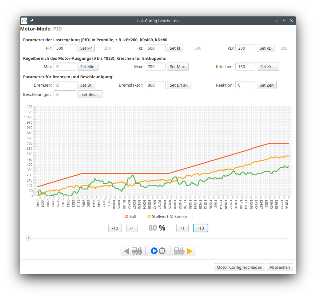
Optimization of braking parameters
For the optimization of the target braking, I use a loop course with a signal before which the locomotive is stopped using 2 balises. The locomotive is in front of the red signal and has 70% set as its speed in the example. Then the signal is opened and as soon as the locomotive has started, it is closed again.
In the following example, you can see the locomotive arriving with 70% (700) (Piko BR 147), then the braking process up to the minimum speed (parameter “Creep” 150), a short time at minimum speed, and on the far right the stop. In the first try, braking factor and deceleration are set to 0:
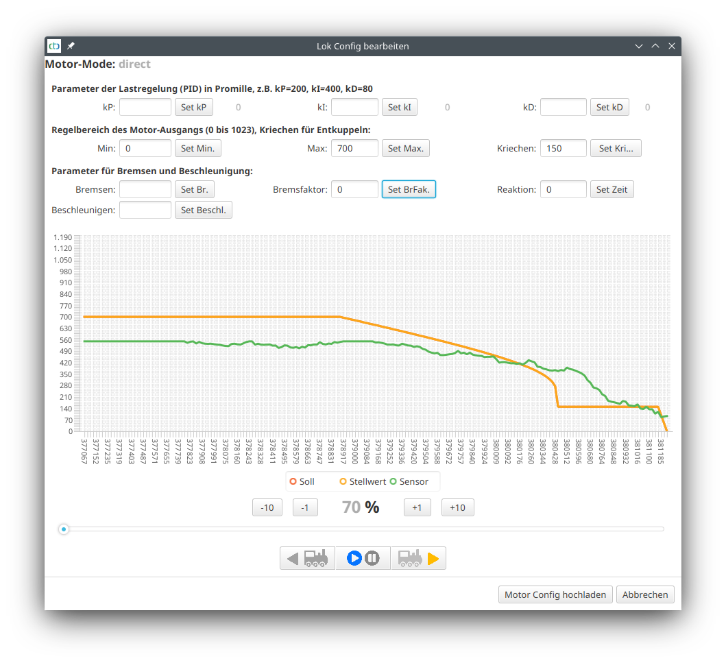
Now the braking curve was optimized and experimentally determined as 800 for the brake factor and 60 for the reaction as optimal values:
Note: Those who want to know in detail will find the “Motor-Setup.csv” data transmitted during the measurement in their user directory. This can be opened with Excel or LibreOffice, for example, and can be evaluated in detail there.
6. Track Diagram Control Panel
The Track Diagram Control Panel allows you to operate turnouts via a schematic representation of the model railway. Track sections are composed of individual (partial) track plans and saved as a “model railway.” The track plans and the model railway are each stored in a CTC-Turnout Module or a CTC-IO Module.
This means a track plan can be created for each contiguous part of a model railway (module, segment) and stored on that part.
The model railway and its components are automatically loaded as soon as the corresponding CTC module connects.
To learn how to use the Track Diagram Control Panel and what the displayed symbols mean, see Chapter 1.6 – Track Diagram: Switching and Status Indicators.
Before a model railway with its track sections can be created, the individual (partial) track plans must first be designed.
A track plan can be used in any number of track sections. However, a turnout, signal, balise, etc., can only be placed in exactly one track plan.
To check which modules already have a track plan or a model railway, open the Module List (or the Configurator). A checkmark appears under “Railway” if a “model railway” is stored on the module. For modules with a track plan, the name of the track plan is displayed in the “Track Plan” column. In the following example of our exhibition layout, a model railway is stored on two modules, and a track plan is stored on three modules:
6.1. Edit Track Plan
Basics
A track plan is initially just a grid with track symbols without any further meaning. The functionality of a track control panel results from the assignment of turnouts, signals, balises, and blocks.
The track plan is stored on the CTC module, from whose configuration dialog the track plan editor is opened (see below). The assignment of turnouts, signals, balises, and blocks is stored in their respective modules. This means, in particular, that changes to a track plan can only be fully saved if the CTC modules of all assigned actions (turnouts, signals, balises, blocks) are reachable via Wi-Fi.
When clicking the “Upload” button, all affected CTC modules (if reachable) are updated based on your changes. The final dialog that appears lists which modules were modified.
Creating a Track Plan
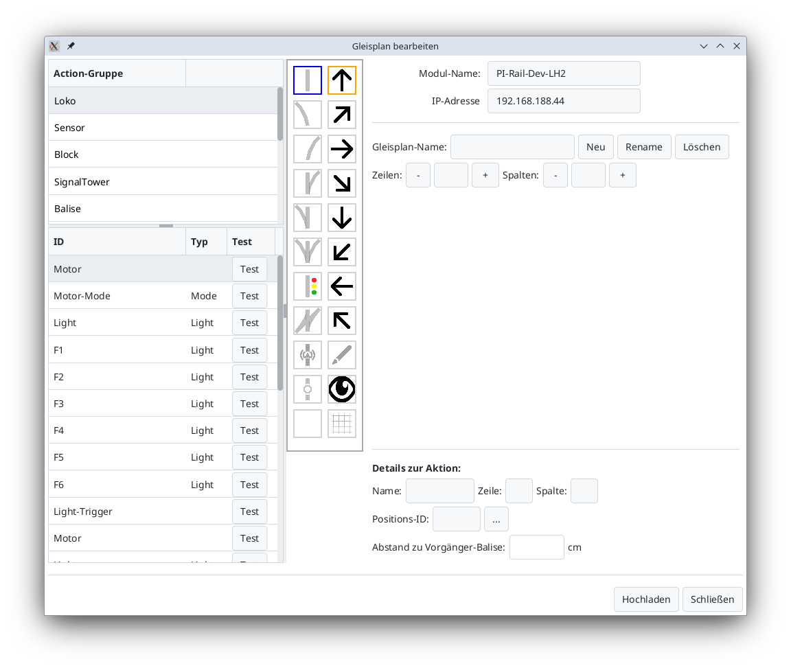
To create a track plan, first select the CTC control module where the track plan should be saved. Open its configuration dialog:
There, select Edit track plan. The following dialog will open:
Use the New button to create a new track plan. Ensure the name is unique.
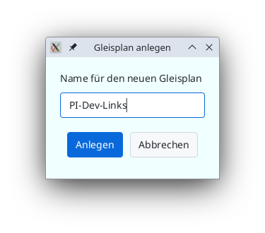
Afterward, a grid will appear where you can place track symbols and later link them with turnouts, signals, etc.
Using the buttons to the right of Rows and Columns, you can adjust the size of the grid.
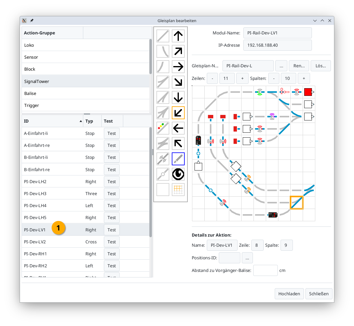
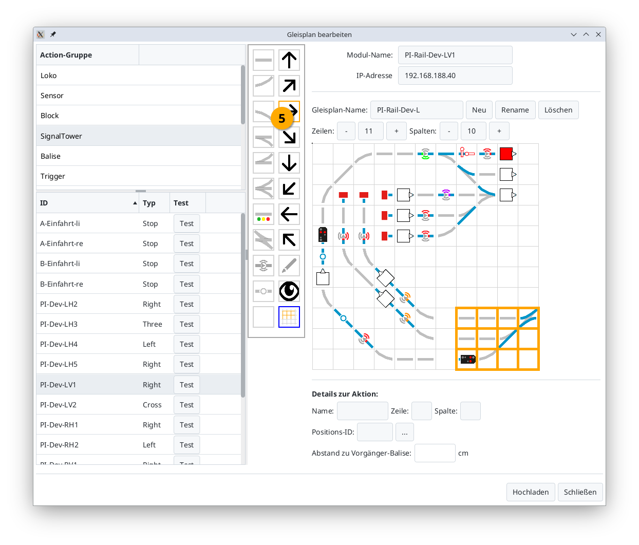
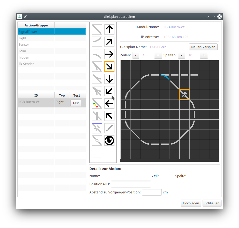
Placing Track Symbols
To place a track symbol, first select the desired track symbol (1) from the left symbol column (in this example, a right-hand turnout). Then, use the arrow symbols (2) to choose the orientation (here, diagonal at 45 degrees). Finally, place the track symbol in the desired position by clicking on the grid (3).
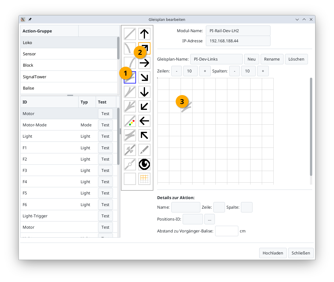
You can now assign a turnout, signal, balise, etc., to the track symbol.
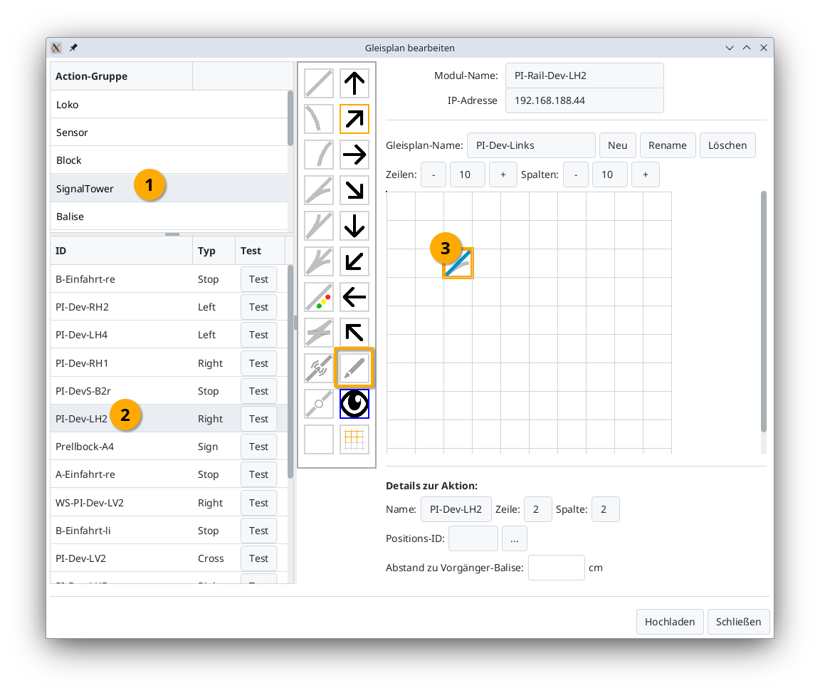
Assigning Turnouts, Signals, etc.
To assign a turnout to a track symbol, first select the action group (1) of the turnout (usually “SignalTower”) in the top-left corner. The list in the bottom-left will now display all actions in the “SignalTower” group (typically all turnouts and signals). Then, click the desired turnout (2). In the tool palette, the pencil icon will automatically activate (highlighted with a thick orange border in the image).
Finally, click the previously placed turnout in the track diagram (3). You’ll know it worked when an orange border appears around the turnout in the track diagram, and the turnout’s current position is displayed in blue.
Notes:
- The action group is predefined when selecting from the CTC product catalog but can be changed at any time in the Config Dialog.
- If the turnout in step (2) is already assigned to a location in the track plan, its position will be outlined in orange.
To locate a turnout in the track plan from the list, click the turnout in the list (1). The corresponding turnout symbol in the grid will then be highlighted with an orange border:
Rotating Track Symbols (from CTC App 4.39 onwards)
If a track symbol has the wrong orientation, you can rotate it by selecting the display symbol (1) (eye). Then click on the track symbol (2) so that it is outlined in orange. Finally, choose the orientation by clicking on the appropriate arrow symbol (3).
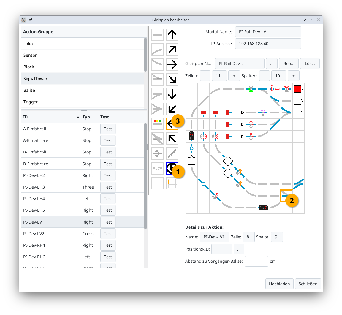
Moving a Section (from CTC App 4.39 onwards)
If you want to move part of your track layout, proceed as follows: First, mark the top-left corner of the section you wish to move by selecting the Display symbol (1) (eye) and then clicking the cell in the track plan (2).
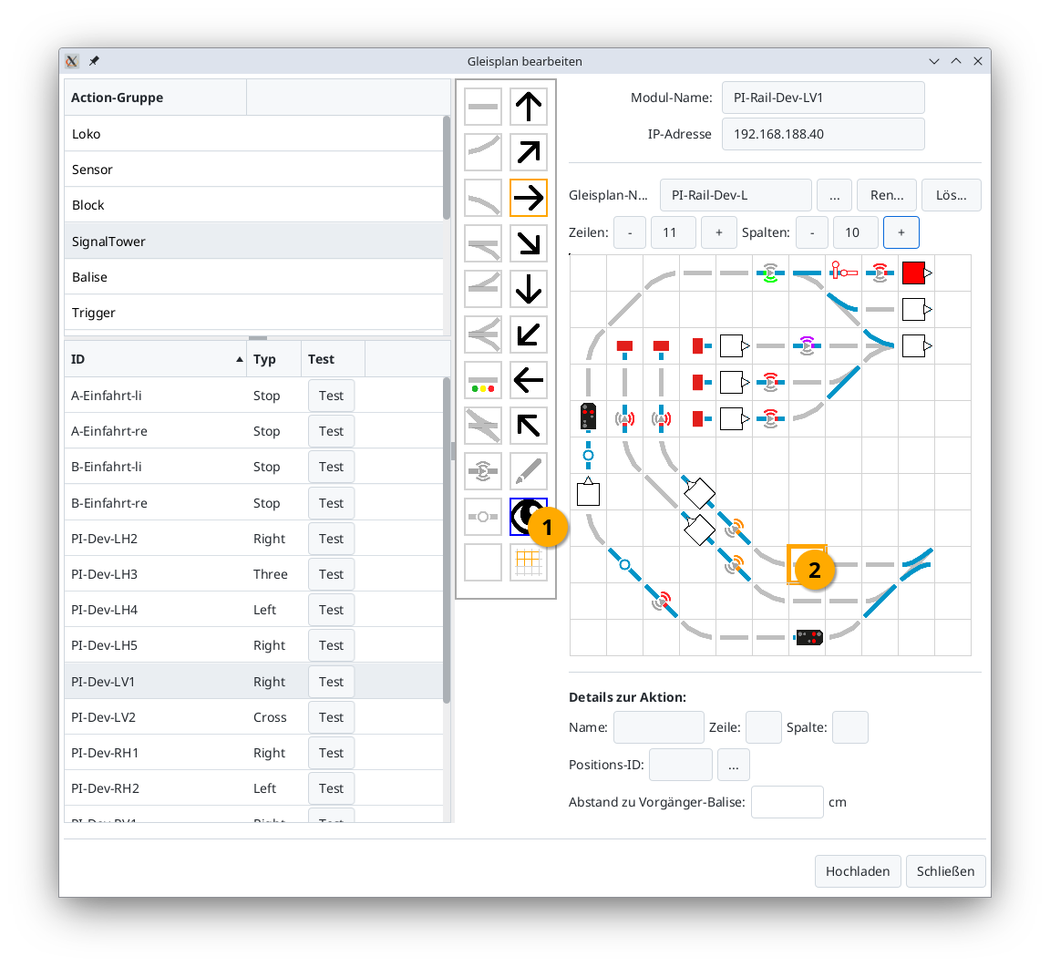
Next, mark the bottom-right corner of the section by selecting the Area tool (3) (grid) and clicking the cell in the track plan (4).
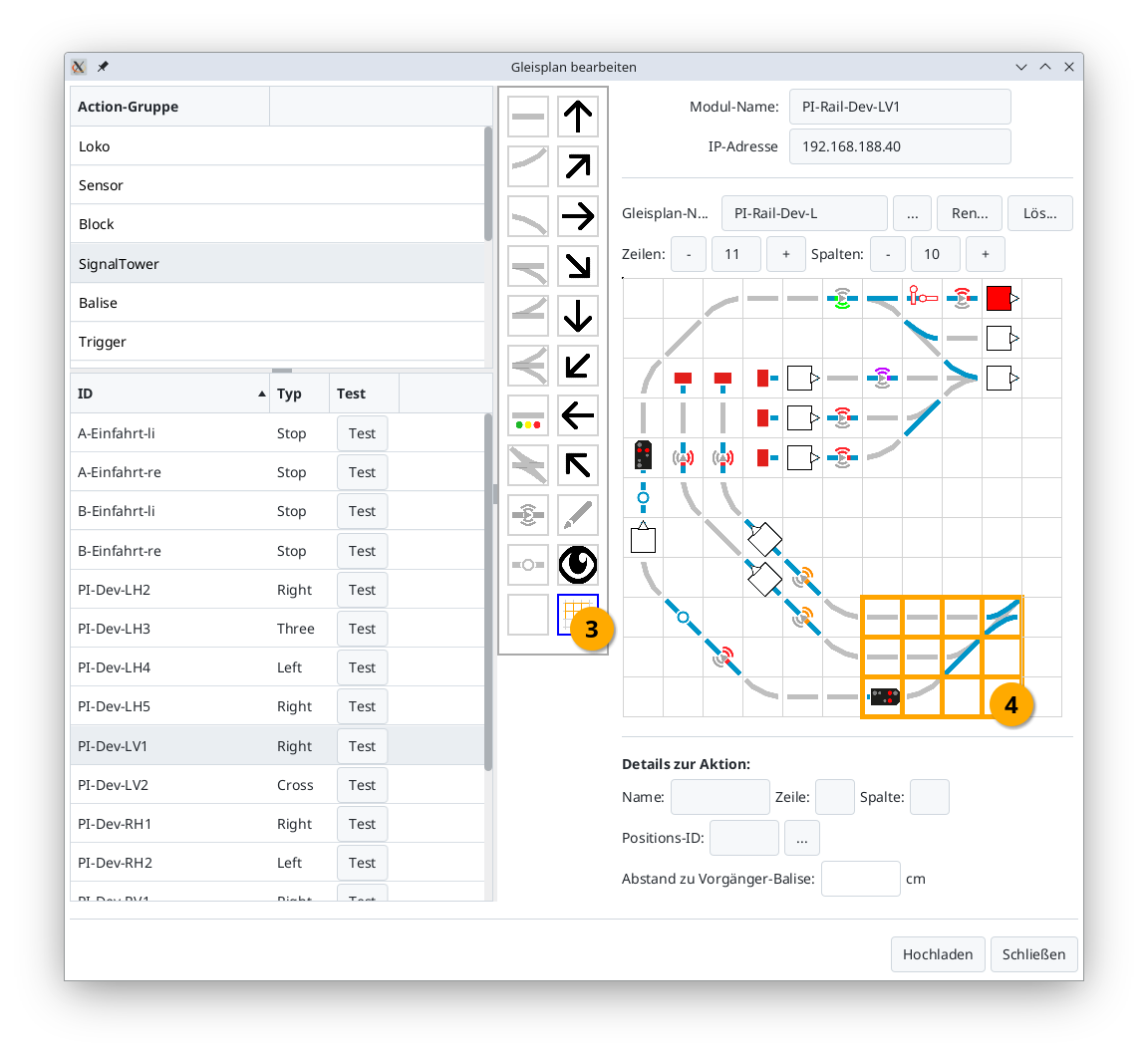
Now you can move the selected section using the arrow symbols in the direction of the arrow. In the example, the right arrow (5) was clicked:
Notes:
- When moving, the assigned actions (turnouts, signals, balises, etc.) are also moved.
- If you move into a non-empty area, the existing content in that area will be overwritten, meaning track symbols and assignments will be replaced. Previous assignments may be lost as a result.
Rename Track Plan (from CTC App 4.39)
Using the “Umbenennen” (Rename) button, you can change the name of the track diagram.
Notes:
- The assignments of turnouts, signals, etc., are automatically adjusted.
- If the track plan is already displayed in a track section, it will not be updated. An error symbol will then appear in the track section.
Delete Track Plan (from CTC App 4.39)
Using the “Löschen” (Delete) button, you can delete a track diagram, including all assignments of turnouts, signals, etc.
Note:
- If the track plan is already displayed in a track section, it will not be updated. An error symbol will then appear in the track section.
6.2. Editing the Model Railway
Model Railway (Overall Plan) – Edit
To create an overall plan, first select the CTC control module where the overall plan should be saved. Open its configuration dialog:

There, select Edit model railway. The following dialog will open:
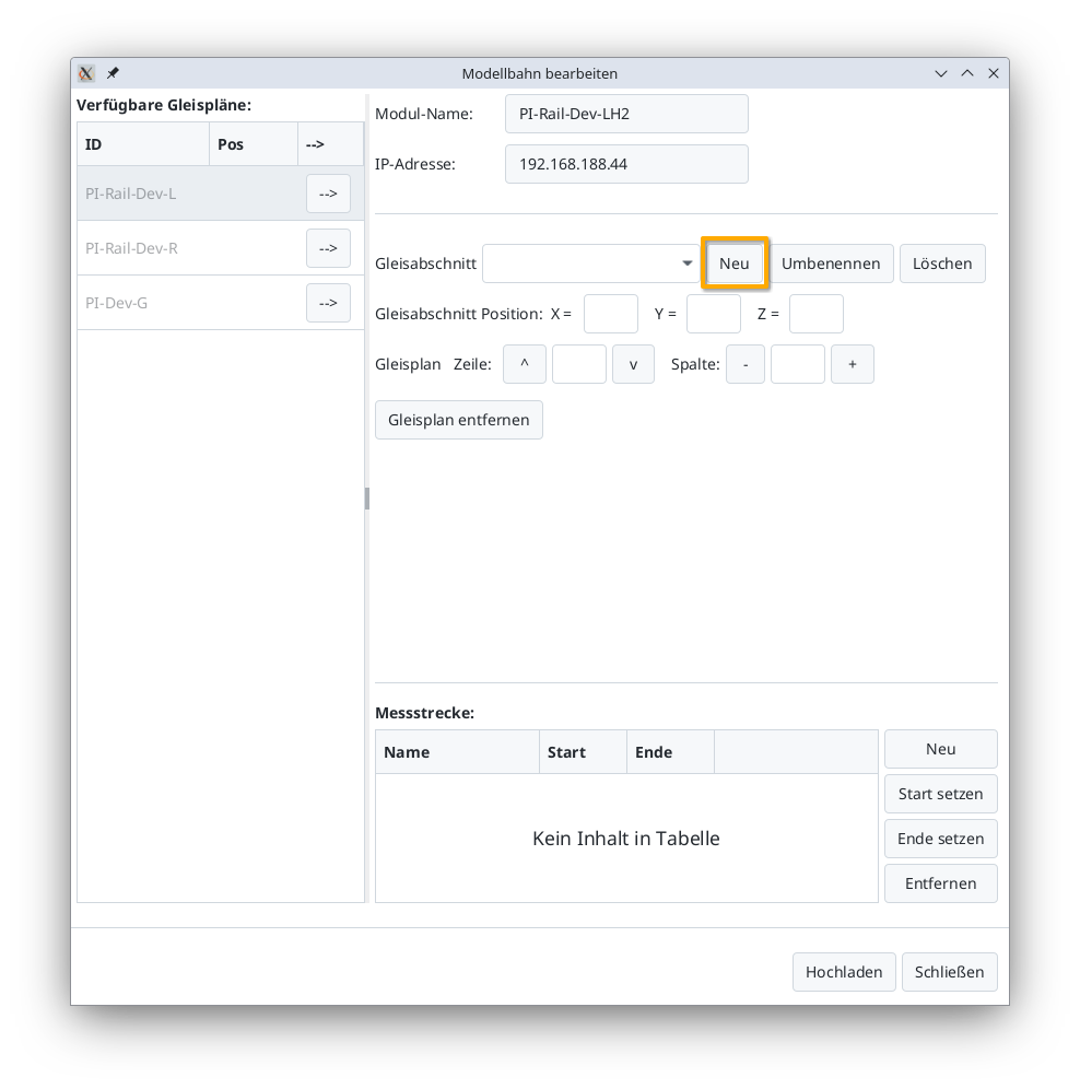
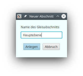
Creating a Track Section
Use the New button to add a track section. Using multiple track sections is recommended for very large model railways as well as for model railways with multiple levels.
Notes:
- Assign meaningful and unique names to your track sections.
- A track plan can also be used across multiple track sections. For example, you can have an overall plan of your model railway and several smaller partial views for mobile devices.
- You can create a model railway on more than one CTC module. The CTC app always displays all track sections from all model railways.
Adding a Track Plan
You can now select the track plans listed on the left (1) and add them to the overall plan using the arrow buttons (2):
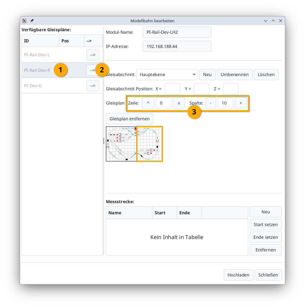
The currently orange-highlighted track plan can still be moved using the buttons (3) next to Row Position and Column. To change the selection, simply click on the desired track plan in the list.
Rename Track Section (from CTC App 4.39)
Using the “Umbenennen” (Rename) button, you can change the name of the track section.
Delete Track Section (from CTC App 4.39)
Using the “Delete” button, you can remove a track section.
Note:
- The track plans placed in the track section will remain intact but may no longer be visible in the panel interface if this was the last placement of the track diagram in a track section.
6.5. Balises (ID Transmitters) in the Track Plan
Creating and Assigning Balises
For Balises (ID transmitters), the symbol shown here is used:
Assigning Balises
In the case of NFC balises, we need to ensure that it has been read by a locomotive at least once before we proceed to the next step. Only then does it appear in the list of balises (ID transmitters) in the track diagram editor.
Now a balise can be assigned to the position in the track diagram. To do this, select the “Balise” (previously “ID transmitters”) action group in the table at the top left and click on the balise to be linked. This will activate the pencil symbol in the toolbar. Now click on the spot in the track plan where the balise is located:
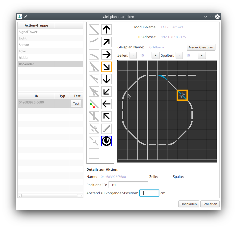
In the case of an IR balise, you are now finished, as its configuration already took place during the configuration of the associated CTC module.
Configuring NFC Balise (NFC Tag)
If it’s a NFC balise, it needs to be configured. To do this, you need to input its Position-ID (3 characters) and the distance to the previous tag.
The following should be noted for the Position-ID:
- The first two characters name the track section to which the tag belongs.
- The third digit or number indicates the order of the tags in a clockwise direction.
7. Automation
With the help of balises (ID transmitters), a basic automatic operation can be set up. To do this, commands are assigned to the balises, which are interpreted by a locomotive equipped with an ID reader when it passes the balise. Balises and ID readers are available for CTC based on IR (infrared) and NFC (RFID). For the following considerations, there is no difference between IR and NFC.
Note: The functionality described here requires the CTC app from version 4.00 and associated locomotive firmware as a prerequisite. Signals and triggers of balises (ID transmitters) configured with older CTC versions must be adjusted. Most of the time, it is easier to remove the relevant lines under “Connected Products” in the Config-Dialog and then add them again.
The basic components of automation with CTC are:
- Driving orders
- Blocks
- Routes
- Timetables
Blocks/Track Sections (Block)
In real railways, blocks are the basis for preventing collisions between trains. The entire track plan is divided into individual blocks (track sections). Turnouts (junctions) may only exist between blocks.
Understanding how block-based model railway control works is essential for understanding automation in CTC. This concept has been nicely described by Dominik Mahrer on modellbahn.mahrer.net.
Signals
Signals, in conjunction with balises (ID transmitters), worked as real train control already in CTC version 3.
If a balise is linked to a signal, it transmits the status of the signal (e.g., Stop) and its distance to the locomotive, which responds accordingly (e.g., stop before the red signal).
With CTC Version 4, it is also taken into account the direction of travel of the locomotive, so it only stops before the red signal if it applies to its direction of travel.
Also, the distance from the ID reader to the front and rear end of the locomotive can be defined within the locomotive. This distance is taken into account during target braking.
By the way, signals are allowed to exist purely virtually, i.e., they can only be seen on the track diagram. No signal is then installed on the layout.
Controlling Signs
Instead of signals, you can also use signs. A sign is added as a product to a turnout like a signal, but does not appear on the control panel and therefore cannot be changed during operation. A sign has no connections, but parameters to determine the sign’s meaning.
With signs as well, you have the option of setting them up virtually, i.e. you only see them in the track diagram. As a result, no sign is put up on the layout.
Paths (Path)
A path establishes a connection between two blocks by appropriately switching all the turnouts in between and finally opening the departure signal of the starting block.
When switching the path, all affected turnouts, signals and blocks are reserved and only released again when a locomotive reaches the block at the end of the path.
Driving Orders (Job)
A typical driving order is the journey from one station to another, possibly with intermediate stops.
The simplest form of a driving order is just a sequence of routes to be switched.
For automatic operation, the driving order can be supplemented with balises (or more precisely their three-letter IDs), which a locomotive should approach in chronological order. A command can also be assigned to each balise.
If the balise also emits a command (e.g. stop in 60cm), the locomotive decides whether it executes the command sent out by the balise or the command recorded in the driving order. For example, a stop always takes precedence over a speed reduction.
A driving order with balises always applies to the locomotive standing in the starting block of the driving order.
Schedules
A schedule is a collection of driving orders that are started at times specified in the schedule (model time). In this way, full automation can be configured.
Configuring Locomotive Sensor
In order for the locomotive to be able to perform a targeted braking, it needs to know how far its ID reader is from the start or end of the locomotive. This is where the two new parameters “dFront” (front) and “dBack” (back) of the ID reader come into play, which define the distance of the ID reader in cm.
Note: When dealing with shuttle trains with the locomotive at one end of the train, when placing your balise on the track, you need to consider that in reverse driving, the ID reader is quite far away from the start of the train.
Processing Events (Triggers)
With so-called triggers, you can respond to events (or state changes) on your model railway, e.g.
- A turnout was switched.
- A signal turned red.
- A locomotive passed a balise.
With a trigger, you determine how to respond to which event. The trigger is always created at the action to be changed by it. You can find out more about this in chapter 4.3 - Linking actions.
Examples
In the following, some typical applications of automation are briefly described. In the “Articles about CTC”, we will gradually publish more detailed descriptions.
Automatic Stop at the Signal
For a CTC locomotive to automatically stop in front of a red signal, a balise is installed in the track at a sufficient distance from the signal. Both the actual braking distance and the distance of the ID reader to the beginning of the train need to be taken into account.
The balise is then linked to the signal and thus each time sends out the state of the signal as a command. The distance to the signal is entered in the trigger’s config. How to configure a trigger can be found in Chapter 4.3 - Linking Actions.
For correct functionality, it is important that the correct direction was chosen when configuring the signal. This is because the locomotive only reacts to commands corresponding to its direction.
Note: By direction of the locomotive, the adjustable driving direction (forward/backward) on the control panel is not meant, but whether it is moving clockwise or counter-clockwise. The locomotive determines this direction from the read IDs.
Automatic Stop with Two Balises
By placing a second balise directly before the signal, you can achieve the locomotive stopping within a few millimeters accuracy. Here, the command “minimal speed” is sent from the first balise with a distance shortly before the second balise. The second balise then immediately (at 0 cm) sends out the command “stop”.
Especially when stopping in sidings, this has the advantage that the locomotive stops above the balise and therefore knows immediately where it is the next time the model railway is switched on.
Stop
A stop at a station is achieved by using two balises. The first one informs the locomotive to slow down to minimum speed shortly before the second balise. The second one then transmits the “Stop” command and how long the locomotive should wait before it continues. Alternatively, the “Reverse” command can be used, where the locomotive continues in the opposite direction after the waiting time.
The commands can be permanently assigned to the balises or transmitted via the locomotive’s drive order.
Alternatively, the locomotive can also be stopped by a signal and only continue its journey with the next entry in the timetable.
Shuttle Train
A shuttle train is enabled by at least two travel orders, namely, outbound and return trips. These are then inserted into a timetable as often as desired.
Scheduled Operation
For scheduled operation, individual driving orders are first created. These can then be individually tested.
Following this, a timetable with departure times is created from these driving orders. Individual driving orders may be used any number of times in this process. However, you must keep in mind that a driving order will only be carried out if there is a locomotive in the start block of the driving order. Depending on which locomotive has been moved to the start block by other driving orders, it is entirely possible that the same driving order will be executed by different locomotives at different times.
7.1. Automation: Blocks
Note: The functionality described here requires the CTC-App from version 4.00 and corresponding locomotive firmware as a prerequisite.
Blocks (Track Sections)
Blocks (track sections) are identified in CTC by two letters/numbers, e.g. “B1”. Uppercase and lowercase letters are considered as different. The first two characters of our balise ID are understood as the name of the block in which the balise is located.
Even if you have not configured a block, there is a suitable block for each balise, namely the one that results from the first two letters of their ID. In order to make a block visible in the track diagram, you must create it. And if you want to create routes, you must create blocks beforehand.
Direction (Clockwise)
Balises in the same block are numbered ascending clockwise at the third position of their ID, for example “AB1”, “AB2”, “AB3” for the three balises in block “AB”. With this numbering, the locomotive can determine the direction (clockwise) in which it is moving.
When placing balises and blocks in the track diagram, you should make sure that the little arrow in the symbol is pointing in a clockwise direction.
Naming Rules
For position IDs, you may only use digits (0 to 9) and letters (A to Z as well as a to z), no special characters and no umlauts. The name of a block must be exactly two characters long. Otherwise, there are no special rules for naming blocks.
On my systems (here the test system), I proceed as follows (block and balise IDs were hand-painted into the track diagram):
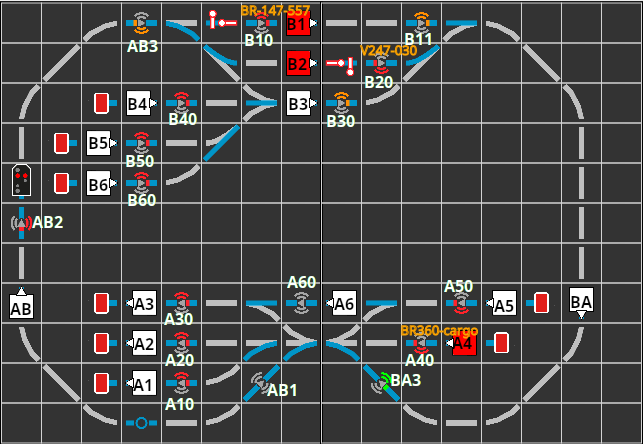
- I start by naming my stations with a single letter, e.g., “A” and “B”.
- Then I assign numbers for the tracks (platforms) of the stations, for example, “A1”, “A2”, “A3”.
- Long connecting routes, consisting of several blocks, are given a separate first letter.
- By using the appropriate lowercase letters, I can, if necessary, name an additional 10 tracks in the station (e.g., “a1”, “a2”).
- For shunting areas and sidings, I might use a new initial letter.
- A track that connects Station “A” with Station “B”, I name “AB”, if it runs clockwise from A to B, otherwise “BA”. Here as well, I have the lowercase letters available if necessary.
Since I have multiple systems (H0-, garden, and several test systems) in the house, I make sure that there are no duplicates - several systems may be active at the same time.
The IDs and further information about blocks and balises are obtained when you click the relevant block:
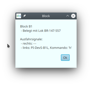
or balise in the track diagram:
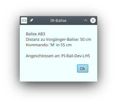
Create / configure block
First, to create a block, select a CTC-turnout module or CTC-Multi-I/O-Board, where the overall plan will be stored. Open its configuration dialogue:
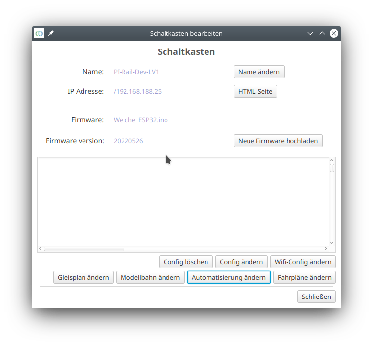
There, click on “Change automation”, then on the plus-button next to “Products and actions”:
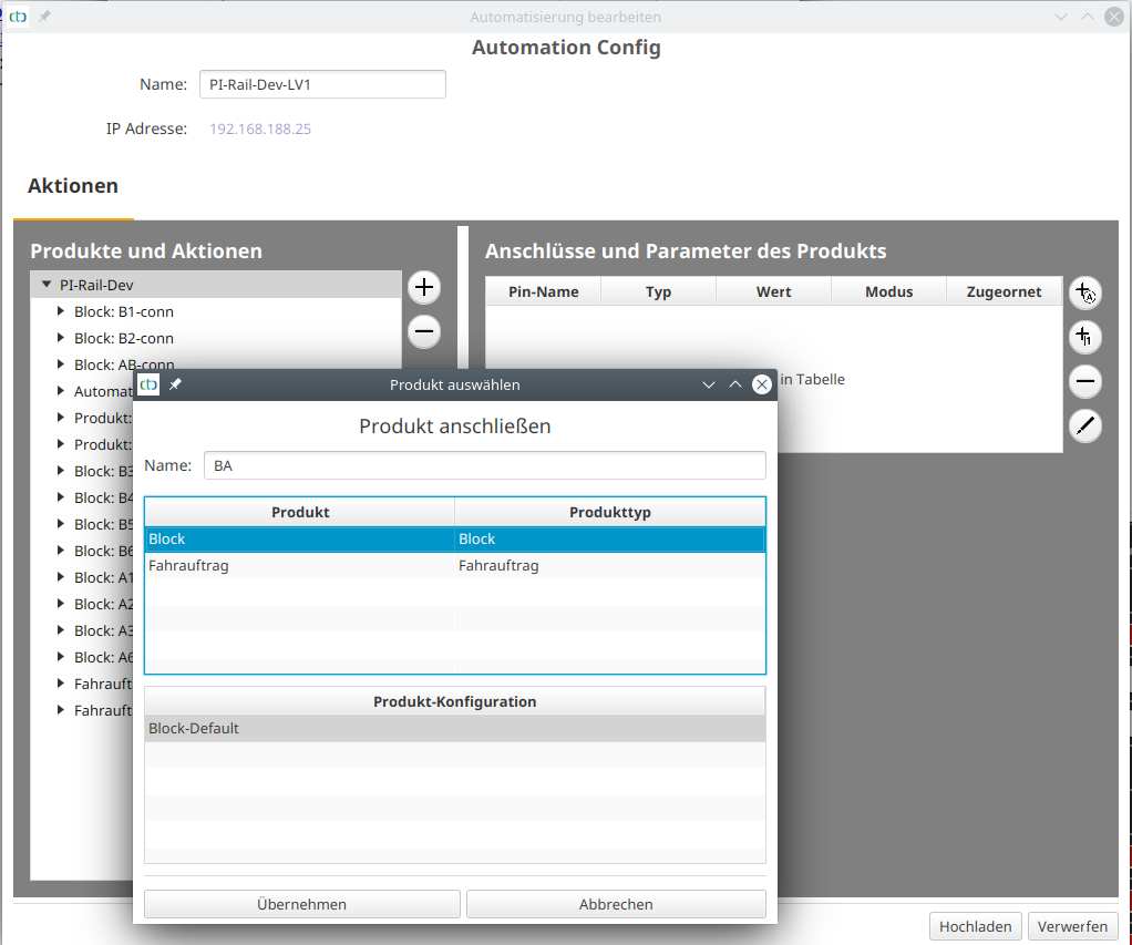
Signals in the Block
For both ends of a block, an exit signal can be defined. This is assigned a position ID, which is the name of the block followed by a plus (‘+’), if it is located at the end of the section in a clockwise direction (right). If the signal is at the other end of the block, it is given a minus (‘-‘).
You can assign a signal to a block by giving the signal a position ID in the track plan editor:
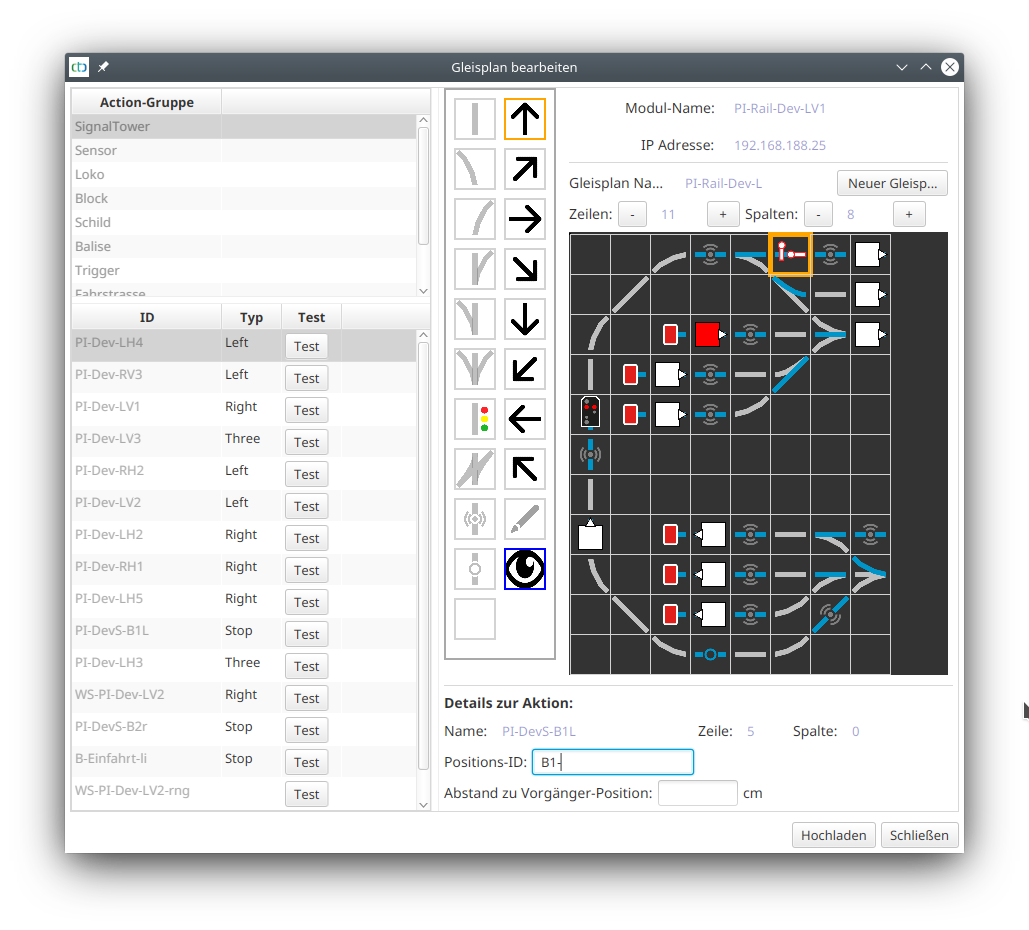
Thus, the CTC app is capable of informing a locomotive which has been brought to a halt in a block due to a red signal, when the signal releases the path again.
Note: To prevent a locomotive from being released by the wrong signal, a maximum of one signal per direction of travel may be assigned to a block.
7.2. Automation: Driving Routes
A driving route establishes a connection between two blocks. To achieve this, all intervening turnouts are set accordingly in the corresponding script.
Configuring Routes
A route is always created at the block where it begins.
For this, select a block in the “Edit Automation” dialog and click on the plus button.
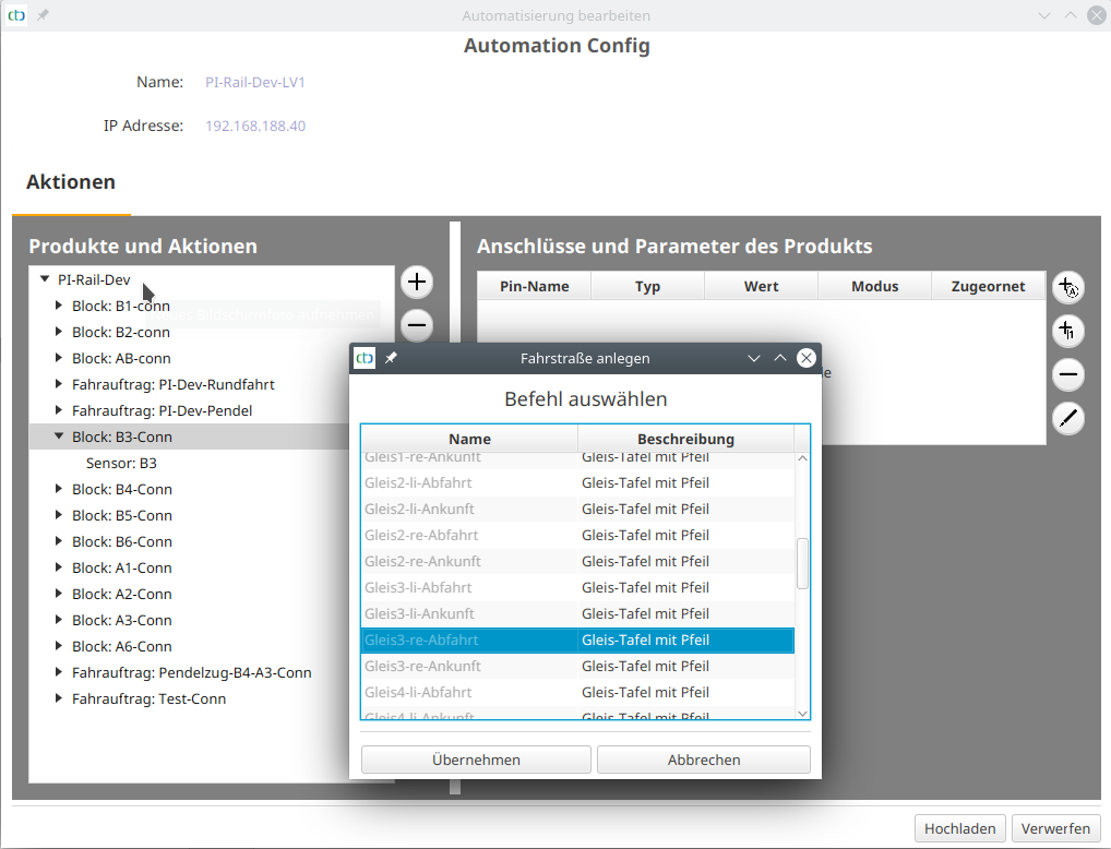
The newly created route group contains a script for “Change to off” (no route active) and a second script for the new route. Select the second route (script) and then click on the button “…” under “End Block” to select the end of the route:
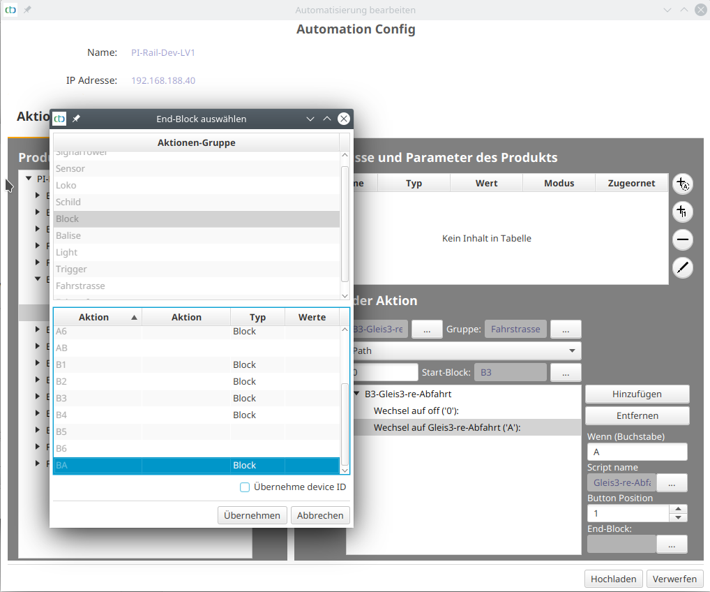
Then click on the “Add” button to determine the first switching command (“call”) of the route:
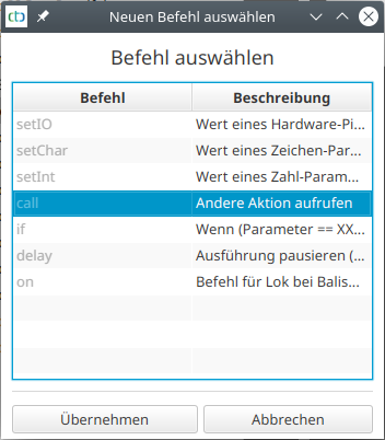
After clicking on “Apply”, the script window switches to the newly created switching command. Then click on the button “…” under “Perform Action” to determine what should be switched.
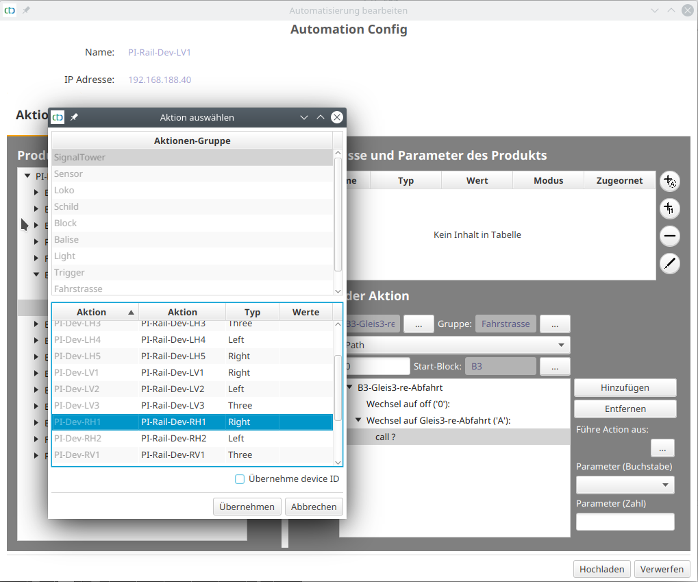
The selection list under “Parameter” is automatically populated with the values allowed by the chosen action. For the turnout in the example, “straight” (straight) is now selected:
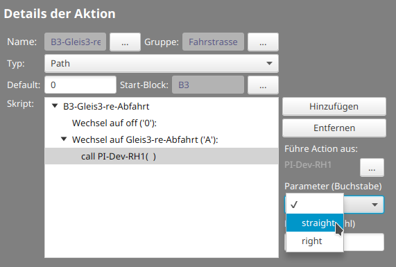
After adding a second switching command, the route looks as follows:
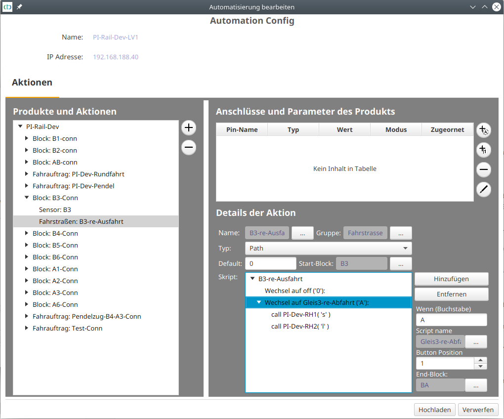
Note: Details on editing scripts can be found in the chapter “Config - Edit Script”.
More Routes
You can add more routes either as a new route group in the respective block or as a new script under an already created route group.
In this context, it is advisable to create all outbound routes from one block in one direction as scripts in a shared route group. For example, for the entrance to the three tracks of the “B” station:
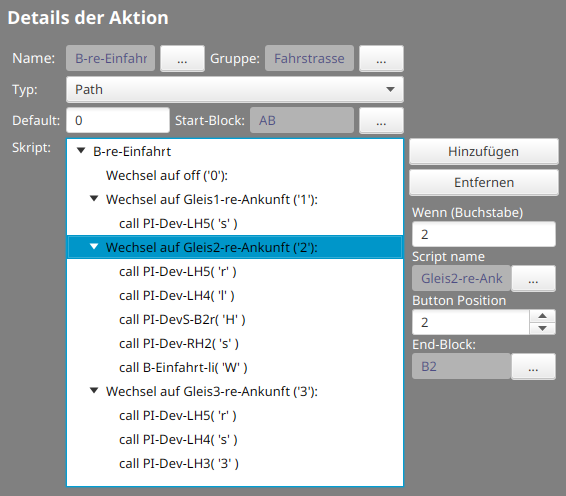
The corresponding line in the control panel then looks like this:

7.3. Automation: Driving Orders
Typically, a driving order (Job) is the journey from one station to another. In the following example, the drive order was set from block B4 via B3 and BA to A3. The reserved turnouts are colored orange and the reserved blocks are colored yellow (block and balise IDs were manually painted into the track diagram):
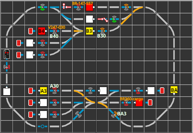
Now, the locomotive V247-030, which is in block B4, can be set in the correct direction and dispatched on its journey by clicking the automatic button.
In our example, only a sequence of routes was defined in the job, but no balises. This works well if all the balises on the route provide suitable information. In our case:
- The balise BA3 was set to the command M;70 (minimum speed in 70 cm) by the route from BA to A4.
- The balise A30 constantly displays the command H;0 (stop immediately).
- The buffer at the end of A3 is assigned as the (clockwise) right exit signal to block A3. This prevents the locomotive from starting off again after reaching block A3.
Upon arrival of V247-030 in block A3, all reservations are withdrawn. The track diagram then looks as follows:
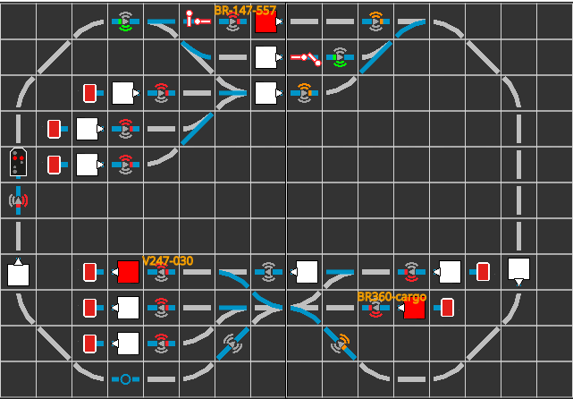
Creating a Drive Order
To create a drive order, we open the “Automation Config”, select the top entry from “Products and Actions”. Then we click on the plus button right next to it:
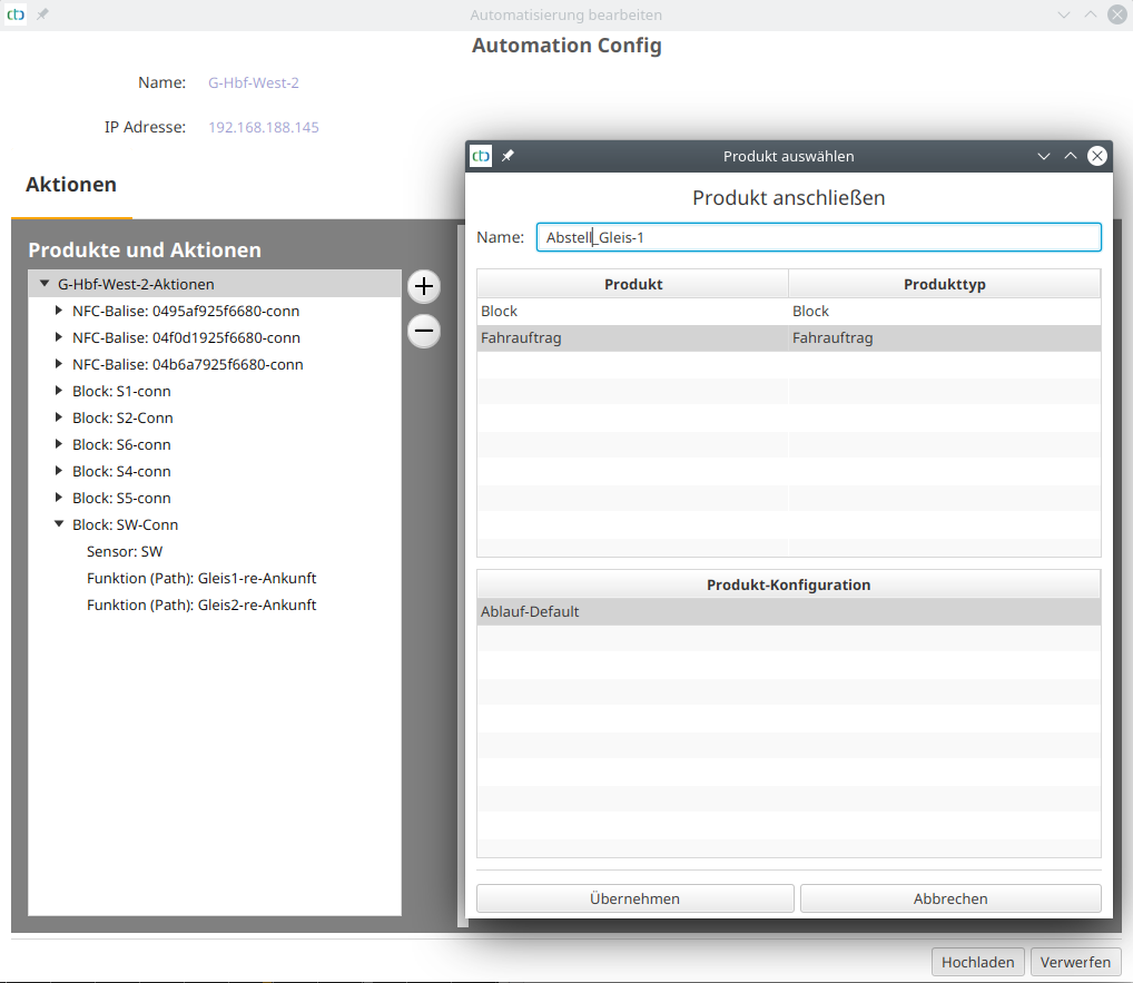
Driving Order with Balise Commands
The following image shows the script for a driving order, in which the balises to be passed are also listed:
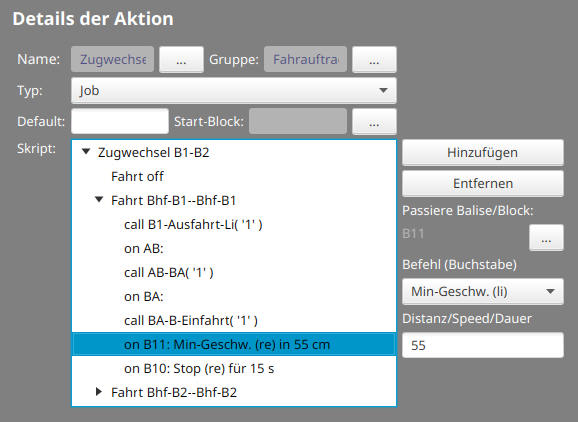
When passing balise B11, the locomotive will slow down to reach the minimum speed after 55 cm. At B10, it will then finally stop for 15 seconds, even if the exit signal clears the way.
7.4. Automation: Timetables
A timetable is a collection of driving orders that are started at the times specified in the timetable (model time).
You can find the timetables as a new tab in the main view of the CTC app:
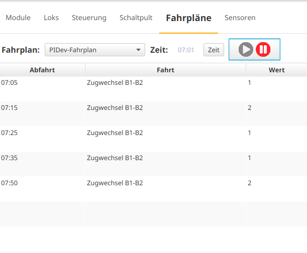
Execute Timetable
To execute a timetable, select it. Then set the model’s clock time using the “Time” button and press the play button to start the clock. As soon as the model’s clock time matches one of the departure times, the associated driving order will be executed.
Creating Timetables
To create a timetable, first choose a CTC-Turnout Module or CTC-Multi-I/O-Board on which the overall plan should be saved. Open its config dialog:
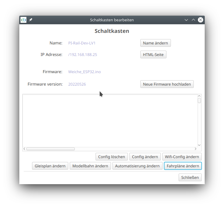
The following dialog appears:
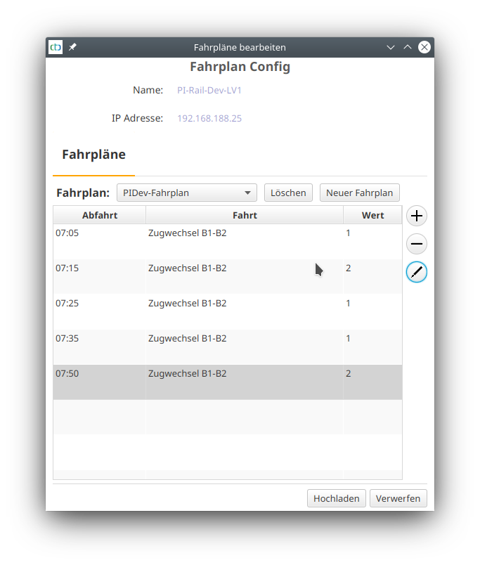
There you click on “New Timetable” to create a new timetable.
With the plus-button, you can add a driving order to the timetable:
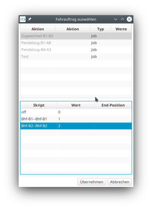
Afterwards, you can change the departure time with the pencil-button.
8. Old Digital: Bridge to DCC & Co.
We are convinced that CT&C is the next generation of model railway control. That’s why we dare to refer to DCC, Motorola format (MM) or Märklin mfx… as “old” or “classic” digital.
Since we can’t develop CTC modules for all imaginable use cases at once, and because we want to enable our customers a smooth transition to CTC, this chapter deals with the various bridges between CTC and old digital systems.
Here are the current ways to connect CTC with the old digital world:
- Parallel operation: CTC locomotives also run with digital power, so they can operate on the same tracks as old digital locomotives at the same time. The controls of both worlds are completely separate in this case.
- Decoder connection: DCC locomotive decoders can be connected to the motor output of a CTC locomotive module and thus be controlled via CTC. This allows beloved sound decoders to continue to be used with CTC, if there is enough space for the additional CTC module in the locomotive. Support for DCC accessory decoders (turnouts, …) and the Motorola-II protocol is in the planning stages.
- Integrating the Z21 center: As of version 4.05, CTC can communicate with digital centers like the Z21 from Roco via the Z21-LAN-protocol. This allows classic digital locomotives, turnouts, etc. to be controlled via a digital center with a Z21-LAN-protocol using the CTC-App.
- Integrating the Z21 handheld controller: also starting with version 4.05, CTC can behave like a digital center with Z21-LAN-protocol. This makes handheld controllers such as the Z21 Wi-Fi Mouse from Roco can be used to control CTC locomotives and switch CTC turnouts.
Of course, for all bridges to the old digital world, it is clear that CTC can only play to its strengths to a limited extent. You will only get rid of the technical limitations of the old digital world when you fully switch to CTC.
Parallel Operation
There is not much to say about parallel operation. CTC modules can be operated with up to 24V DC, digital current and also AC. More about this in the separate document “Power Supply and Router”
In this case, the old digital locomotives and turnouts are controlled as before, and the CTC modules are controlled via the CTC apps. A connection between both worlds is not anticipated in this scenario.
8.1. Old Digital: Integrating DCC Decoders
Most CTC locomotive modules can generate a DCC signal via their motor output and thus behave like a mini digital command station.
Locomotive Decoders with DCC
Converting a locomotive is quite straightforward if there is enough space for the additional CTC module: The track connection of the digital decoder is connected to the motor output of the CTC locomotive module, and the CTC locomotive module is connected to the track connection in the locomotive. The article “Conversion of PIKO BR 50 with DCC Sound” describes the conversion and configuration using the example of a garden railway locomotive from PIKO.
The configuration of a DCC decoder connected in this manner is described in Chapter 4.6 “Config - Connecting a DCC Decoder”.
Turnout Decoders with DCC
This functionality is in planning - please contact us if needed.
CTC Locomotive Module as a DCC Command Station
This functionality is in planning - please contact us if needed.
With our CTC-Locomotive module-G, a small model railway layout can be supplied with power and digital signal.
Märklin: Motorola-II and mfx
Support for Motorola-II (MM2) would provide access to nearly all Märklin decoders with sufficient functionality. Especially since newer Märklin decoders can also be fully addressed via DCC.
The implementation of Motorola-II is in planning - please contact us if needed.
If we come across a suitable library, support for the Märklin mfx format is also conceivable.
8.2. Old Digital: Integrating Z21 Control Center
Using the Z21-LAN-Protocol, the CTC-App can control locomotives and turnouts connected to a digital control center. The digital locomotives and turnouts need to be configured once and can then be controlled like normal CTC modules through the CTC-App. The configuration is stored in any CTC turnout module or CTC multi-IO board.
The digital control center must of course support the Z21-LAN protocol and be reachable by the CTC-App via LAN or WLAN.
Prerequisite for this function is the CTC-App version 4.05.
Configuring Z21 Locomotive
To store the configuration of the digital locomotive controlled via the Z21-LAN protocol, we select any CTC turnout module or CTC multi-IO board. We then go into the config dialog of the CTC module:
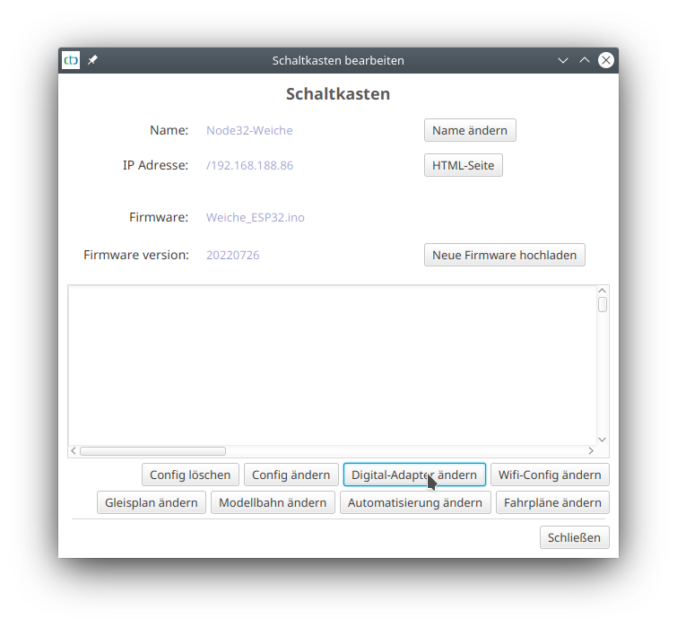
Click on “Change Digital Adapter”. The following dialog opens:
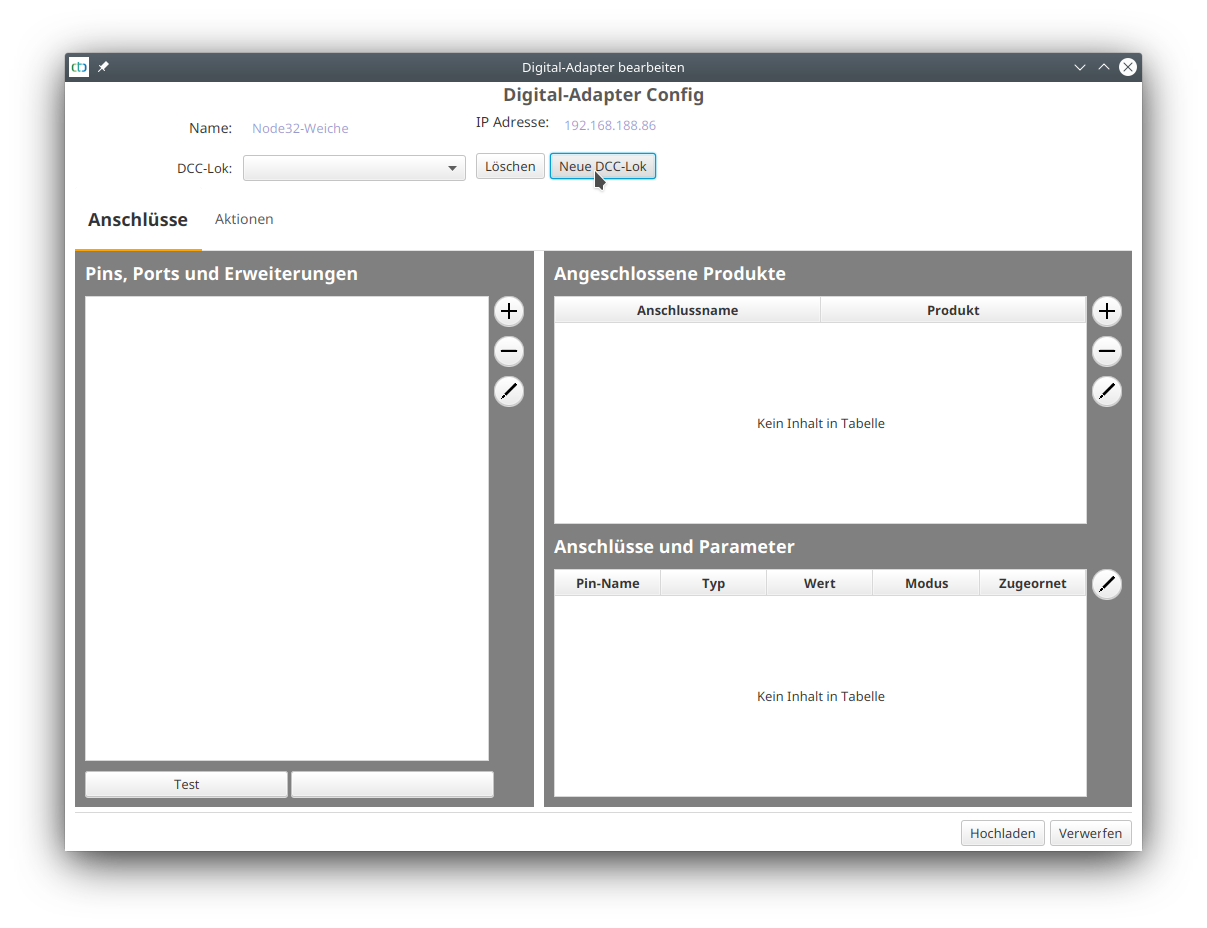
We click on “New DCC Locomotive” and enter the name under which the locomotive should appear later. I chose the prefix “Z21_” to distinguish the locomotives controlled by the Z21 from real CTC locomotives.
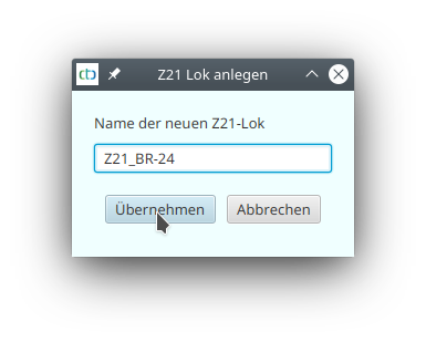
Then we click on “Apply”. Under “Pins, Ports, and Extensions” the line “Connections” appears. We mark this and click on the plus button next to it. In the dialog that opens, we enter the IP address of the Z21 control center:
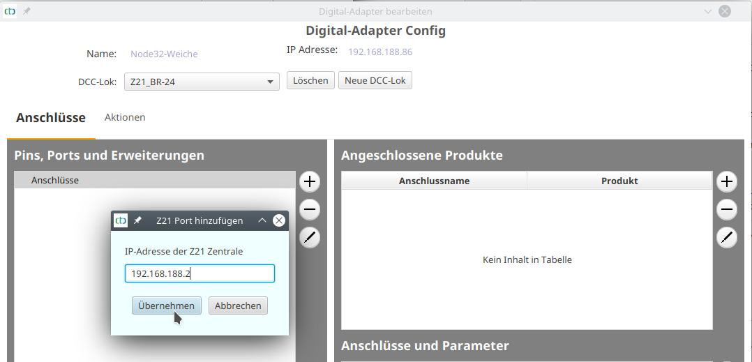
Then we select the newly created port with the IP address and click on the plus button again. We select the extension configuration “dcc.xml”. In the dialog that opens, we enter any name - we only see it in this configuration. In the Bus Address field, we enter the DCC address of our locomotive - in the example, this is the DCC default “3”. In the list, we select “DCC Locomotive”:
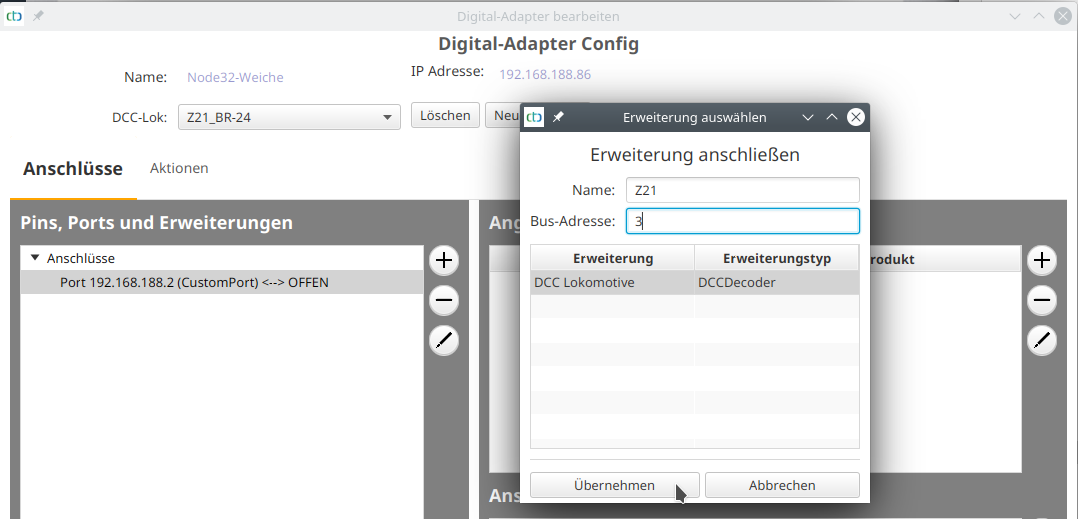
Then we click on “apply”. The locomotive was created and motor and headlights are configured:
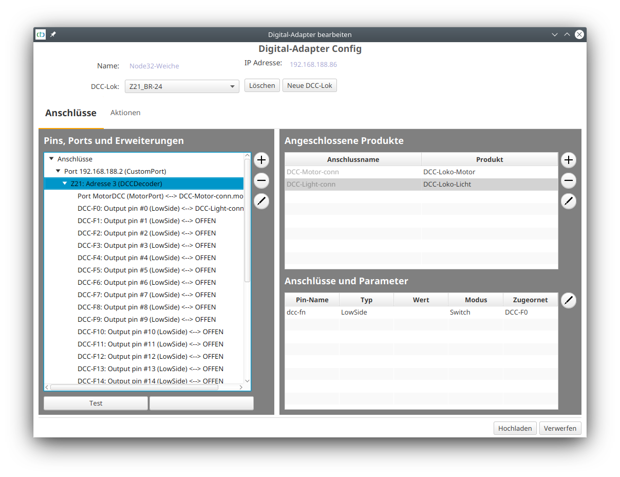
Now, additional functions, e.g., sound can be configured. This is done exactly the same way as with a DCC decoder connected to a CTC locomotive module, see Chapter 4.6 “Config - Connecting DCC Decoder”.
After saving, the digital locomotive appears in the list of CTC modules:
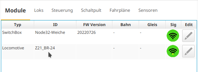
8.3. Using Z21 Hand Controller
Through the menu item “Start Z21 Central,” the PC version of the CTC App can activate the emulation of a Z21 central unit. In this case, the CTC App responds to commands received via the Z21 WLAN protocol and forwards them to CTC modules.
Notes:
- Starting with CTC App version 4.05, it is possible to control the speed and functions of a locomotive.
- Starting with CTC App version 4.06, turnouts can also be switched.
- We have tested with Roco’s WLAN mouse and Roco’s Z21 Android app.
Set Locomotive Address
The locomotive address is set by opening the config of the locomotive and adding the parameter “dccAddr” to the main motor:
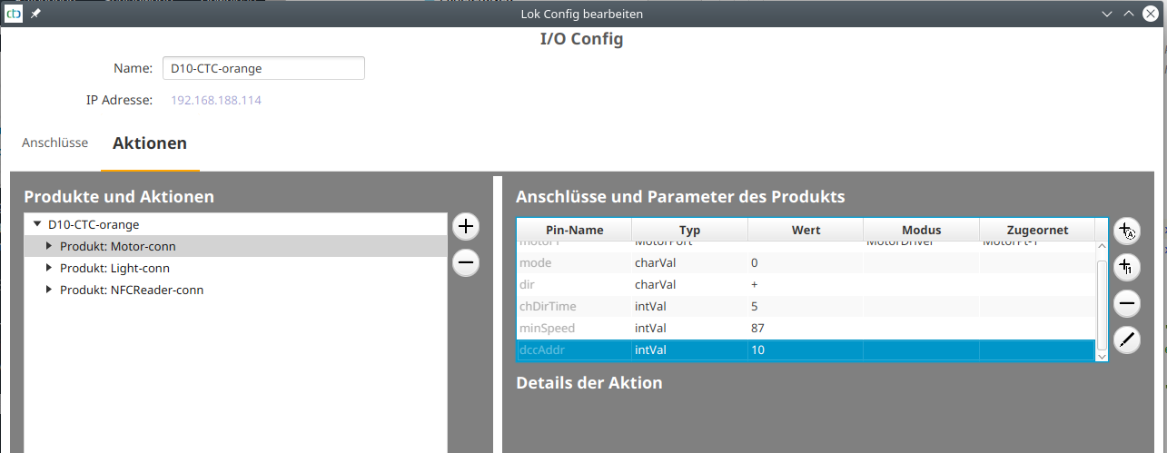
Assign Locomotive Function
To assign locomotive functions to the DCC function numbers, go to the config of the locomotive. There, you select the function to be linked with a DCC function and add the parameters “dccFx+” and “dccFx-“, where “x” stands for the function number. Then set the value of the StateScript at “dccFx+” for “function on” and at “dccFx-“ for “function off.”
In the example, DCC F0 was assigned to the function “Light” and specified that it should call script “1” (on) when on and script “0” (off) when off:
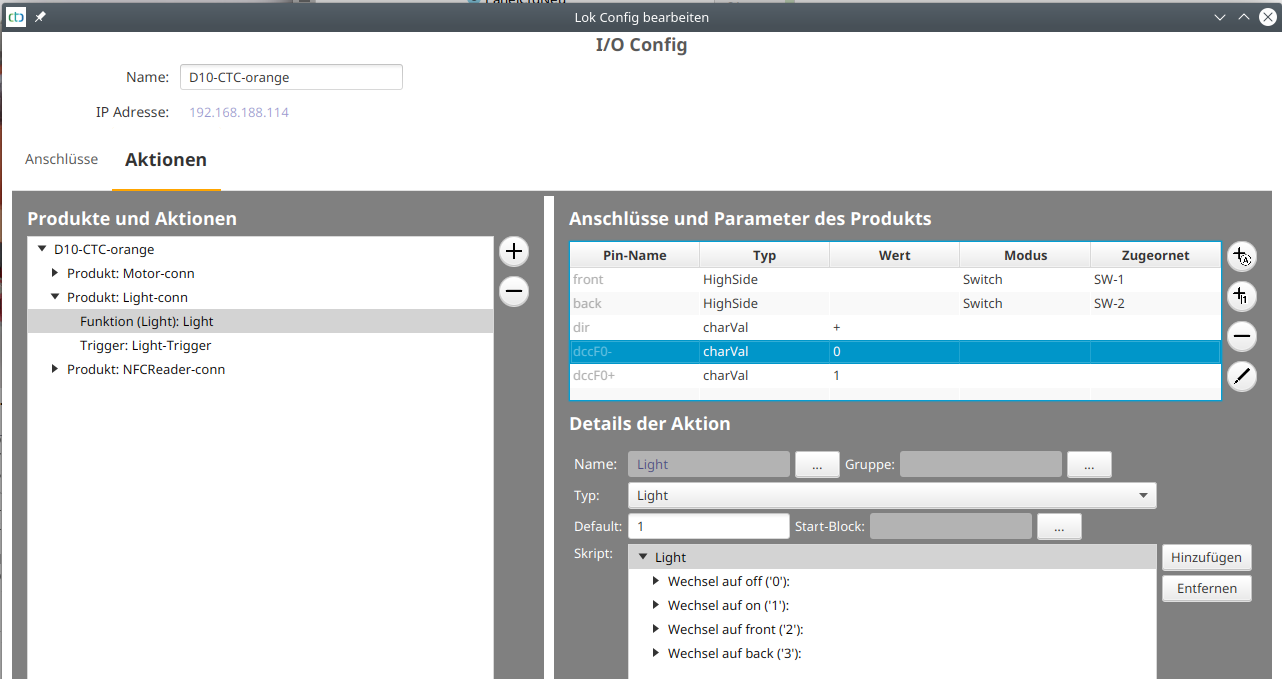
Driving Locomotive
Once the Z21 central is started and the hand controller is configured to the IP address of the CTC App, all CTC locomotives with a “dccAddr” can be controlled.
The DCC address is displayed under “Locomotives” in the column “Nr.” starting with CTC App version 4.06.
Note: The locomotive can only be controlled if it is set to manual control in the CTC App.
Set Turnout Address
The turnout address is set by opening the config of the turnout and adding the parameter “dccAddr” to the function:
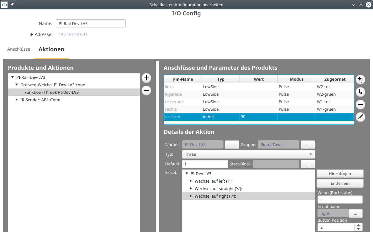
The scripts of the function are assigned in the order indicated by “Button Position”:
- 0 for dccAddr “off”
- 1 for dccAddr “on”
- All others for the “on” state of the addresses following dccAddr. In the screenshot above, address 31 “on” is for the script at position 2 (“right”).
8.4. Model Railway Control Software via Z21
Through the menu item “Start Z21 Control Center”, the PC version of the CTC app can activate the emulation of a Z21 control center. The CTC app not only responds to commands received via the Z21 WLAN protocol, but also reports whenever a locomotive passes a balise (occupancy report).
This provides all the functionality necessary to connect CTC with a model railway control software like iTrain. We can gladly demonstrate how iTrain can be connected to CTC at our exhibition booth.
You can learn how to assign addresses for locomotives and turnouts, as well as the locomotive functions, in the previous chapter “Using Z21 Throttle”.
Setting Balise Address (Occupancy Detector)
Balises appear in the Z21 LAN protocol as CAN occupancy detectors.
These also require an address, which is entered on the balise in the CTC app. Here, we also use the parameter “dccAddr”:
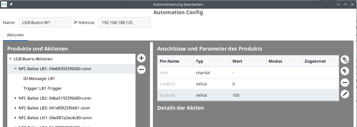
9. Sound
If you want CTC modules to also inspire with sound, you must rely on existing digital technology. By now, there are several possibilities to do this:
- CTC locomotive modules can generate a DCC signal. In this way, either the digital decoder that came with the locomotive can be continued to use, or a new digital decoder can be connected. You can find more information about this in Chapter 8.1 - “Old Digital: Integrating DCC Decoders”
- From the firmware (20230902) supplied with CTC App version 4.19, the SUSI3 interface can be retrofitted for all CTC locomotive modules (except for CTC-Lokmodul-H0a). For locomotives that have originally used a SUSI3 module for the sound, the original sound can remain, without the need to keep the original decoder. This can be done, for example, with PIKO’s G scale model of the BR50. Learn more about SUSI sound in Chapter 9.1 - “Sound with SUSI Interface”
9.1. Sound with SUSI Interface
The SUSI interface allows the separation of decoder and sound module. In the meantime, there are tiny SUSI sound modules and even speakers with built-in SUSI sound modules. This means that even in tight spaces, the chances are good to enjoy locomotive sound with CTC.
The SUSI interface can currently be retrofitted to all CTC locomotive modules (except CTC locomotive module H0a). You only need the latest firmware (at least 20230902) and the CTC app version 4.19 or newer.
The SUSI module must handle 3.3 Volt signal levels and tolerate track voltage as its power supply. The support from Uhlenbrock has confirmed these data for the current IntelliSound 6 Modules.
Since our existing CTC locomotive modules do not have a SUSI socket, an appropriate adapter must be made for them. How this is done is documented below and in our locomotive conversions. If required, we will be happy to create a suitable adapter for you.
Original Sound
There are locomotives that use a SUSI module for sound by default. In this case, you can directly control the motor and locomotive functions with CTC and still enjoy the original sound of your locomotive. This works, for example, with PIKO’s G scale model of the BR50.
Retrofitting Sound
If you do not value the original sound or if the locomotive to be upgraded to CTC did not have any sound, you can purchase a SUSI sound module and connect it to the CTC locomotive module.
The Märklin BR247, which always accompanies us to our exhibitions, has now been equipped with SUSI sound. Details can be found in the BR247 conversion report.
SUSI Adapter for CTC Locomotive Modules
The four pins of the SUSI-classic socket must be connected as follows:
- Plus (red) to VBB
- Ground (black) to GND
- Data (grey) via a minimum of 470 Ohm resistor to a GPIO pin of the processor
- Clock (blue) via a minimum of 470 Ohm resistor to a GPIO pin of the processor
Adapter for CTC Locomotive Module 21mtc
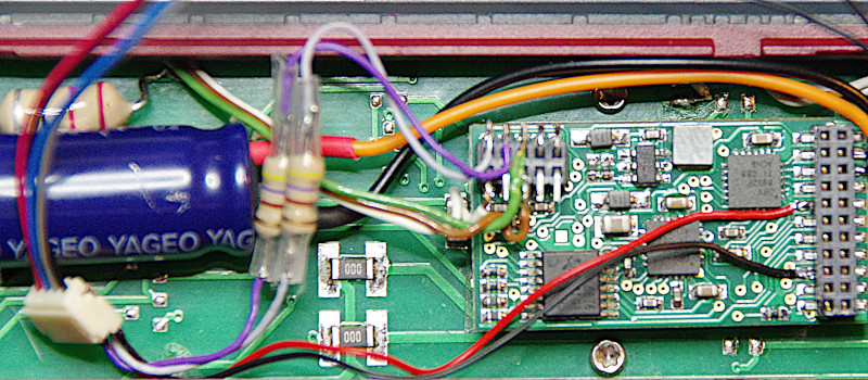
For the CTC locomotive module 21mtc:
- Clock (blue) is connected to “Input-1 (Pin 33)” on the additional socket, and
- Data (grey) is connected to “Input-2 (Pin 32)” on the additional socket.
Additionally, we need to connect Plus (red) to VBB and Ground (black) to GND:
- In the picture, we did this directly at the solder pads of the 21mtc socket.
- Alternatively, the much larger solder pads intended for the support capacitor on the other side of the CTC locomotive module can be used.
Adapter for CTC Locomotive Module PluX22
For the CTC locomotive module PluX22:
- Clock (blue) is connected to “NFC TX (Pin 25)” on the additional socket, and
- Data (grey) is connected to “NFC RX (Pin 23)” on the additional socket.
Additionally, we need to connect Plus (red) to VBB and Ground (black) to GND:
- This can be done directly at the solder pads of the 21mtc socket, as with the 21mtc.
- Alternatively, the much larger solder pads intended for the support capacitor of the CTC locomotive module can be used.
Adapter for CTC Locomotive Module G
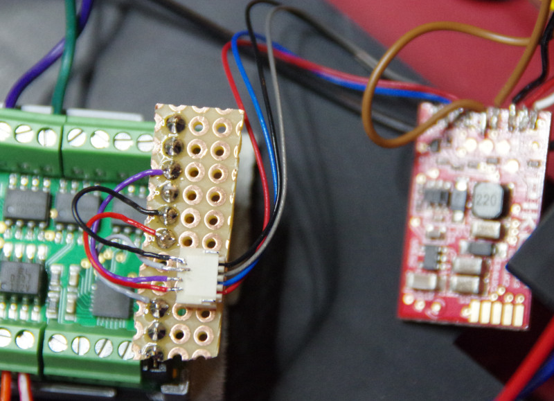
For the CTC locomotive module G, we use the servo connections:
- Clock (blue) is connected to “Servo-2 PWM”.
- Data (grey) is connected to “Servo-1 PWM”. Since the servo connections on the CTC module are already equipped with a 1 kOhm resistor, no separate resistor is needed here.
Via the socket intended for the 5 Volt voltage regulator, we can connect Plus (red) to VBB and Ground (black) to GND.
10. Wagon Recognition (Axle Counter)
Starting from CTC-App version 4.22, an NFC-Reader can be mounted beneath the track to recognize wagons equipped with an NFC-Tag. This provides CTC with an adequate replacement for axle counters - with the advantage that the app knows exactly which wagon has just passed by.
The CTC-NFC-Reader can be mounted under a track and connected to a CTC turnout module or CTC Multi-IO Board.
Wagons equipped with an NFC-Tag can thus be read. Subsequently, they can be assigned to a depot. There, an image and the data of the wagon (name, length, etc.) are stored. A depot can be established at any CTC turnout module or CTC Multi-IO-Board.
10.1. Configure Wagon Detection
To configure the wagon detection, connect an “NFC Reader” from the product catalog “universell-sensoren.xml” to a CTC turnout module or a CTC Multi-IO Board.
In the config for the CTC turnout module or CTC Multi-IO Board, connect the NFC Reader to the “NFC-Port” connection. If the “NFC-Port” is not present, you must update the firmware of your CTC turnout module or CTC Multi-IO Board to the latest version. Afterwards, you can replace the IO configuration, see “Chapter 4 - Configure Modules”.
Note: You can only connect either the second IR sender or an NFC Reader to a CTC turnout module or CTC Multi-IO Board, which means before connecting the NFC Reader, you must ensure that IRPort-2 is not being used.
Next, place the NFC Reader in the track plan and assign it a position ID like a balise (3 characters). If the NFC Reader is placed directly next to a balise, you can use the balise’s position ID.
10.2. Engine Facility (BW)
In the real-world prototype, the engine facility (BW) serves as the home for locomotives and cars. In CTC, it is primarily the car management, i.e., here the IDs of the NFC tags attached to the cars are linked with a picture, name, etc.
Creating an Engine Facility
To create an engine facility (BW), open the configuration dialog of the CTC turnout module or CTC Multi-IO board where you want to store the BW. There, click on “Create Engine Facility (BW)”. The following dialog will appear:
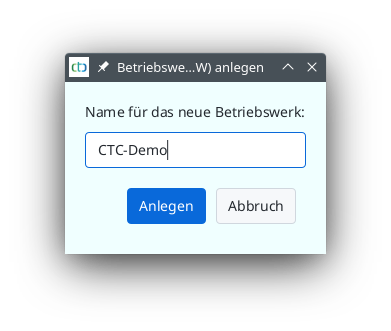
Enter a name - as a suggestion, you will see the name of the CTC module. Then click “Create”.
From now on, you can manage the cars of the new BW via the “BW Display” view.
Displaying an Engine Facility
You can open the BW display via the “View” menu:
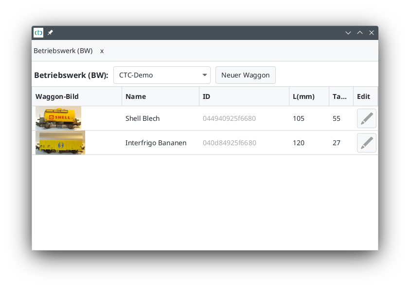
Behind “Engine Facility (BW):” you will find a dropdown list with all the engine facilities of your model railway.
Adding Cars to a BW
First, run a new car over the NFC reader. Then, the ID of the NFC tag is known to the CTC app, and you can enter the rest of the car’s data.
Note: For a read tag to be recognized as a new car, the NFC reader must be assigned to a block. You do this when placing the NFC reader in the track diagram, similar to creating NFC balises.
To do this, click on “New Car”. A list of all unassigned NFC tags will appear:
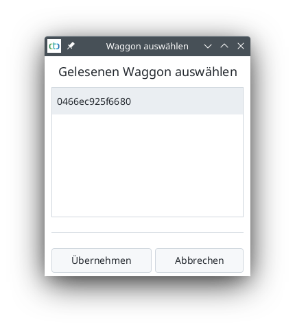
Select the tag and click on Adopt:
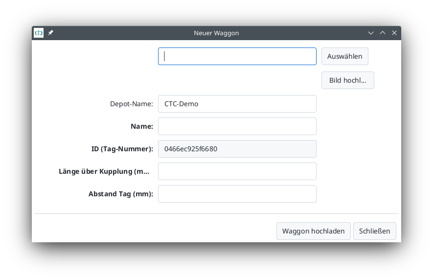
Now you can select the car’s image, give the car a name, as well as enter the length of the car and the position of the tag.
As soon as you click “Upload Car”, the car is stored in the engine facility (on the CTC module).
Editing a Car
To edit a car, click on the pencil icon to the right of the car in the car list of the engine facility. The following dialog will appear:
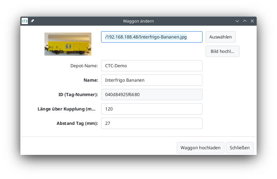
A1. Appendix - Error Handling
For more information on this topic, see the Troubleshooting FAQ section.
The status indicator (LED or headlight) is described in Chapter 7 - Module Status Indicators.
Log Output from CTC Modules
As of CTC App version 4.19 and the corresponding firmware, the log messages from the CTC modules are transmitted to the CTC App and displayed in the configuration dialog—see “Log Output” in Chapter 4 “Configuring Modules”.
This is where you will also find notes on configuration errors, for example. Additionally, these outputs can help us narrow down the cause of an issue when you submit a support request.
To view the messages from the startup of a CTC module, follow these steps:
- Open the CTC App and power on the relevant CTC module.
- Open the configuration dialog for the CTC module.
- Turn off the power to the relevant CTC module for a few seconds, then turn it back on.
- As soon as the CTC module reappears in the CTC App (Wi-Fi symbol green), the startup messages from the CTC module will appear in the log output.
Configuration Files of the CTC Modules
The easiest way to download and back up the configuration files of all CTC modules is via the “Settings / Config Backup” menu item in the CTC app (desktop). Here, you select a folder on your hard drive as the backup folder. Afterward, a subfolder named after each accessible CTC module will be created in this backup folder, containing all the configuration files for that module.
When submitting support requests, it is often helpful to include the configuration files of the affected CTC modules.
CTC App Log Files
For support requests or error reports, the CTC app’s log file is often very helpful to us. The desktop app creates a folder named “CTC-App” in your user directory (personal folder), with a subfolder called “logs” inside it. There, you will find the log file under the name “pi-rail.log”.
Below, we’ve compiled instructions on how to locate your user directory. Sometimes, I wonder if certain operating system manufacturers should stick to making novelty items instead of software.
User Directory on Linux
On Linux, the user directory (user home) is /home/USER, where USER represents your username.
All common file explorers for Linux open in the user directory by default.
There, you will find the folder “CTC-app” containing the “logs” subfolder:
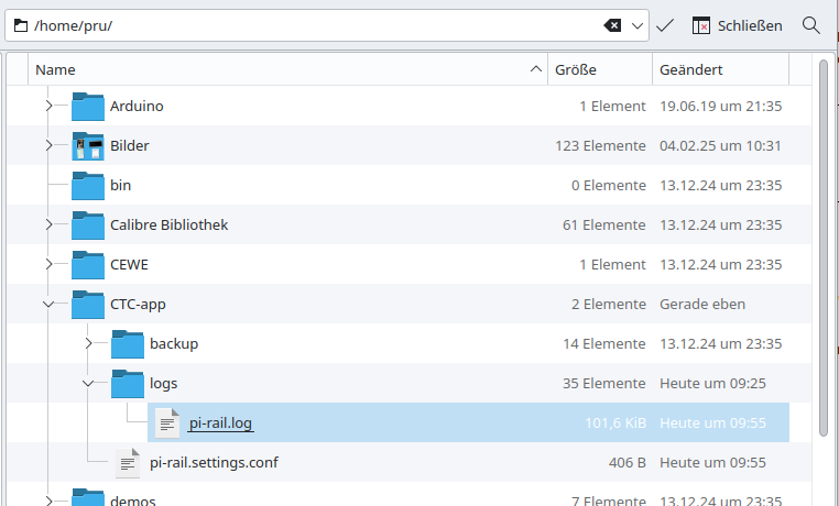
User Directory on macOS
Apple plays a nice little game of hide-and-seek with you. Here, the user directory is assigned as “/home/USER/Library/Application Support”. To access this folder in Finder, click the “Go” menu and then press the ALT (Option) key. Suddenly, a new menu item “Library” appears—click it. After that, Finder behaves as expected: Click the “Application Support” folder, then “CTC-App”, and finally “logs”.
User Directory on Windows 10
In Windows, the user directory is (currently) prominently placed in the left pane of File Explorer. Directly below Desktop, one of the first entries is a folder with your own name (in this example, “pi-rail”). After that, things get a bit unclear.
Here, you’ll find the “AppData” folder, and beneath it, “Roaming”. Once there, open the “CTC-App” folder, and then the “logs” folder:
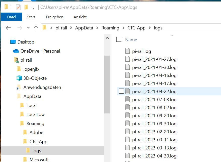
The log file without a date in its name is from today. For all others, the date is encoded in the filename (Year-Month-Day).
User Directory on Windows 11
On Windows 11, the logs are located in the same place as on Windows 10, but the Windows Explorer interface looks slightly different again. Start with the “C:” drive and open the folder with your name under “Users” (here, “pru”). Below that, you will again find “AppData,” followed by “Roaming,” and finally “CTC-app” with the “logs” folder:
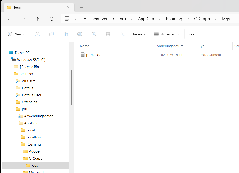
A2. Appendix - HTML Page
HTML Page
The HTML page provides direct access to the XML configuration files of the CTC module.
WARNING: Incorrect settings in the XML files, especially the “ioCfg.xml”, can permanently damage the CTC module and also the connected locomotive/turnout/…!
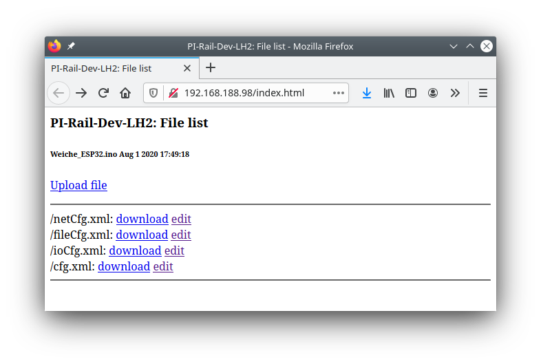
Download
To download a config file, click the download link next to the name of the config file.
Depending on your browser settings, the file will land in the browser’s download folder, or you will be asked for the save location.
In this way, you can both secure your configuration and send us your configuration in case of a support issue.
Note: When you change the config with the CTC app, these changes will be saved in the “cfg.xml” file of the CTC module. In the “netCfg.xml” you will find the SSID and password of your model railway’s WLAN.
Upload
To upload a config file, click the Upload file link.
In the desktop app delivery, you will find the appropriate ioCfg.xml for each module type (firmware) in the Config folder. The netCfg.xml, fileCfg.xml, and (empty) cfg.xml are identical for all CTC modules.
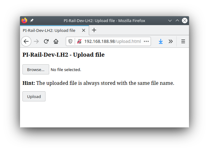
Note: After each upload, the CTC module restarts, meaning it takes a few seconds before it becomes visible again.
Edit
By clicking on edit, you reach a simple text editor. In the ZIP file of the desktop app, sorted by module type, you will find appropriate configuration files, whose content you can use as templates for your own configurations. Editing the text in an editor that can handle XML (e.g., Notepad++) reduces the risk of creating faulty configurations.
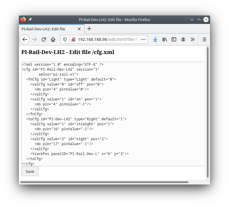
After clicking Save, the CTC module confirms the reception of the configuration file and then resets itself.
A3. Config - Create Product Catalog
To create a product catalog, you need an XML editor and the associated XML schema files.
Please contact us if you want to create your own product catalog.
A4. Cable Colors
Unfortunately, there are quite a number of standards and manufacturer conventions regarding the color coding of cables and connectors. In this chapter, we make a determination from a CTC perspective for cables that you will find on CTC modules and in modules modified by us.
Note: We adhere to these color rules from July 2021. Unfortunately, we only thought about cable colors too late, which means that for everything delivered by us before July 2021, you cannot rely on the cable colors following a system!
From our perspective, the following assignment is generally expected:
- Negative pole: black or blue
- Positive pole: red
Therefore, we decided against using blue for the positive pole in the locomotive. You can find other color standards here:
In the following, we understand “marking” to mean the color of a connector or a shrink sleeve at the end of the cable.
Single Cables
Locomotive Installation
| Cable Color | Marking | Description | Polarization | Standard |
|---|---|---|---|---|
 brown brown |
- | Track left / both tracks | undefined or ground | Märklin |
 red red |
- | Track right / middle rail | undefined or phase | NEM 658, Märklin |
 black black |
- | CTC module or decoder negative pole | negative (GND) | - |
 orange orange |
- | CTC module or decoder positive pole | positive (VBB) | Märklin |
 green green |
- | Motor left | changing | Märklin |
| green |
 white white |
AUX high-side | switched positive (VBB) | - |
 grey grey |
- | Motor right | changing | NEM 658 |
| grey |
white |
Light front high-side | switched positive (VBB) | - |
| grey |
 yellow yellow |
Light rear high-side | switched positive (VBB) | - |
 purple purple |
- | AUX low-side | switched negative (GND) | AUX 2: NEM 658 |
| white |
- | Light front low-side | switched negative (GND) | NEM 658 |
| yellow |
- | Light rear low-side | switched negative (GND) | NEM 658, Märklin |
Model Railway Layout
Turnout modules, IO-boards, signals, …
| Cable Color | Marking | Description | Polarization | Standard |
|---|---|---|---|---|
| brown |
- | Track left / both tracks | undefined or ground | Märklin |
| red |
- | Track right / middle rail | undefined or phase | NEM 658, Märklin |
| green |
- | Turnout with polarity change or motorized: drive left | changing | Märklin |
| grey |
- | Turnout with polarity change or motorized: drive right | changing | NEM 658 |
| black |
- | Turnout/light: negative pole | negative (GND) | |
| yellow |
- | Turnout/light: power supply / positive pole | positive (VBB) | Märklin |
 blue blue |
green |
Turnout: ground drive position straight | switched negative (GND) | Märklin |
| blue |
green |
Semaphore signal: ground drive position green | switched negative (GND) | Märklin |
| blue |
red |
Turnout: ground drive position turning | switched negative (GND) | Märklin |
| blue |
red |
Semaphore signal: ground drive position red | switched negative (GND) | Märklin |
| white |
- | Signal line or LED | Processor positive (3.3V) |
Multi-conductor Cables
IR Balise
At the turnout module, 4-conductor cable (white, brown, green, yellow) with socket strip at 2.54mm pitch. At the IR balise (track) 2-conductor cable with pin strip at 2.54mm pitch.
| Cable Color | Marking | Description | Polarization | Standard |
|---|---|---|---|---|
| brown (IR-1) / green (IR-2) | green |
IR balise: negative pole (TX-GND) | TX signal | - |
| white (IR-1) / yellow (IR-2) | red |
IR balise: positive pole (PWM-VCC) | PWM signal | - |
IR Receiver in Locomotive
3-conductor cable with angled 8-pin header at 1.27 mm pitch.
| Cable Color | Marking | Description | Polarization | Standard |
|---|---|---|---|---|
| black |
red |
IR receiver: negative pole (GND) | negative (GND) | - |
| red |
- | IR receiver: positive pole (VCC, 3.3V) | positive 3.3V (VCC) | - |
| purple |
- | IR receiver: TXD | Serial data | - |
NFC Reader
Wires soldered to NFC reader.
| Cable Color | Marking | Description | Polarization | Standard |
|---|---|---|---|---|
| black |
- | NFC reader: negative pole (GND) | negative (GND) | - |
| red |
- | NFC reader: positive pole (VCC, 3.3V) | positive 3.3V (VCC) | - |
| green |
- | NFC reader: TXD | Serial data | - |
| blue |
- | NFC reader: RXC | Serial data | - |
Notes:
- Please contact us if you have any uncertainties - it is usually cheaper than repairing.
- We gladly accept additions that you think are missing.
Other Links on Cable Colors
Here are some links that we have looked at and based our colors on.
Standards:
- NEM 658 - Electrical Interface PluX12 / 16 / 22
- NEM 650 - Electrical Interfaces for Model Vehicles
- NEM 605 - Layout Wiring
Märklin-Collector-Infos.de (Peter Roland):
The Moba (Wiki):
B.01. Appendix B: Examples
In this chapter, various examples are presented.
The goal is to demonstrate how configurations are constructed for typical scenarios. A very detailed step-by-step guide can be found in the separate document “CTC-Starter-Sets”, which we highly recommend reading before studying these examples.
B.02. Config Example: Timed Stop
In this example, a timer is used to make a train stop for a certain period of time with the help of a light signal, e.g., at a station.
The starting point for this example is a signal linked to two balises: one for slowing down and a second for precise stopping. How this works is described in Chapter 4.3 “Config - Linking Actions” for both IR balises and NFC balises.
For the timed stop, you add two timers and a trigger to the signal.
The trigger should activate when any locomotive reaches the balise directly in front of the signal and stops there. To do this, open the signal’s config, click on the signal under “Actions,” and then click the plus button to the right of “Products and Actions”:
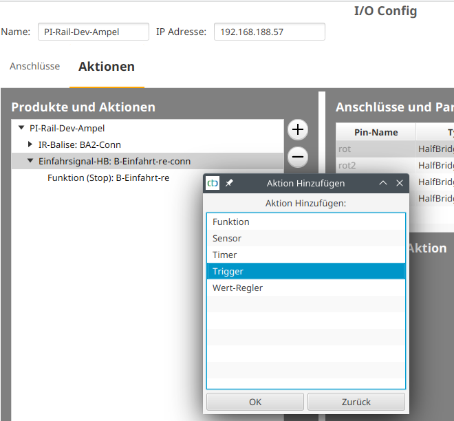
Then select “Trigger” and click “OK.” In the example, the new trigger is called “B-Entry-re-trg.”
In the same way, create the two timers “B-Entry-release” and “B-Entry-block.” After creating them, give the new action a suitable name by clicking the “…” button next to Name in “Action Details.” Only then do you edit the individual scripts.
For the trigger, click the “Source” button to select the balise as the source of the event. The actual trigger for the event is the locomotive. Since the timing should work for any locomotive, nothing is selected under “Trigger.” The star next to “on (MAC)” appears automatically after selecting the source.
The letter passed to the script is the command that the locomotive received from the balise. You use this to start the timer for changing the signal to green only when the locomotive was stopped (‘h’). The second “if” responds to all other commands and does nothing except reset the trigger so it can react again on the next stop.
To start the timer in the script for stop (‘h’), click the line “If ‘BA2’ from * == ‘h’” and then click “Add.” In the popup, select the command “call.” You can then choose the previously created timer “B-Entry-release” from the list under “Execute action”.
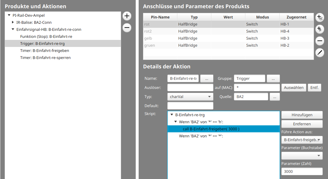
Note: A trigger only activates if the value passed to it differs from its own value. For this, the trigger stores the last received value. You can see the value of a trigger on the control panel by selecting the appropriate action group (usually “Trigger”):
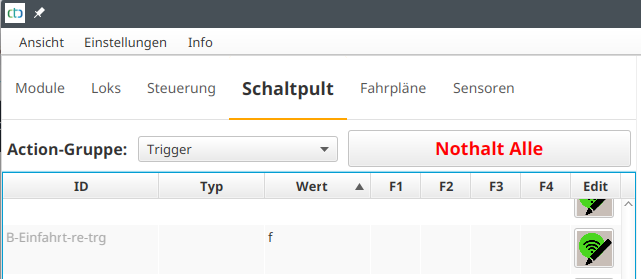
The timer for opening the signal (“B-Entry-release”) only receives a single command. Namely, a call to the green function (Hp1_Light) of the light signal:
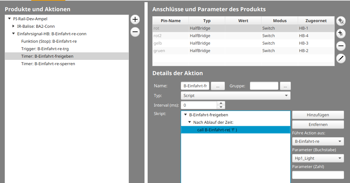
To ensure the light signal returns to red after the locomotive passes, add the call to the timer for closing the signal (“B-Entry-block”) to the function “Hp1_Light (‘f’)”:
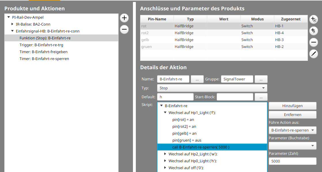
The timer for closing the signal (“B-Entry-block”) also receives a single command. Namely, a call to the red function (Hp0_Light) of the light signal:
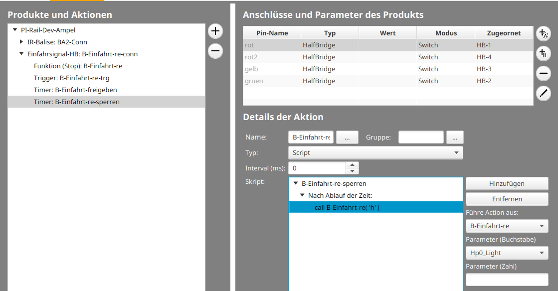
B.03. Config Example: Signal Dependent on Turnout Position
In this example, a trigger is used to set a signal to red when the associated turnout closes the route.
The starting point for this example is a signal and a turnout configured using the product catalog. How this works is described in Chapter 4.1 “Config - Connecting Products”.
In the example, the semaphore signal should turn red when the turnout is set to straight.
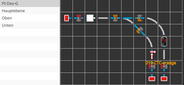
To do this, open the config of the signal by right-clicking on the signal in the track plan. Then switch to the “Actions” tab and select the signal (here PI-Dev-G-Signal). Next, click the plus button to the right of “Products and Actions”. The following dialog opens:
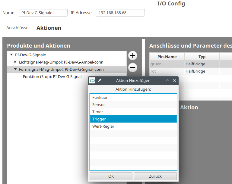
There, choose “Trigger” and click “OK”. Then click the “…” button next to the name of the trigger to give it a suitable name:
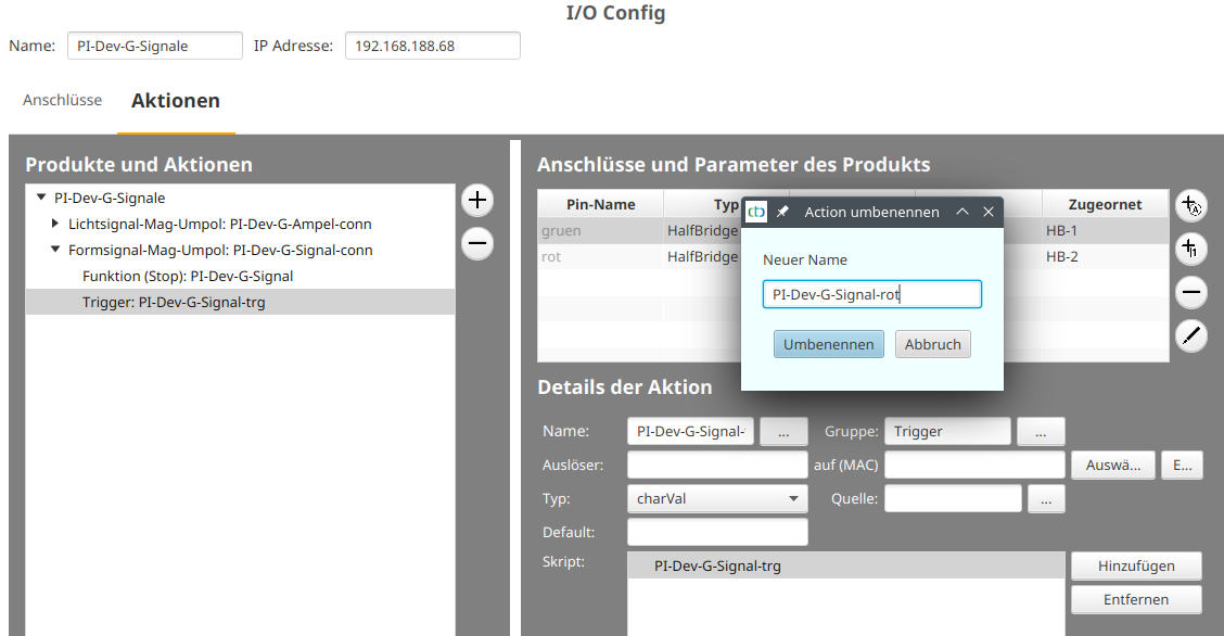
Select the turnout as the trigger (here PI-Dev-Turnout-G) by clicking the “select” button. Usually, you will find turnouts in the “SignalTower” group. However, in the example of our exhibition layout, the turnouts and signals of Gauge-G were moved to a separate group “PI-Dev-G”:
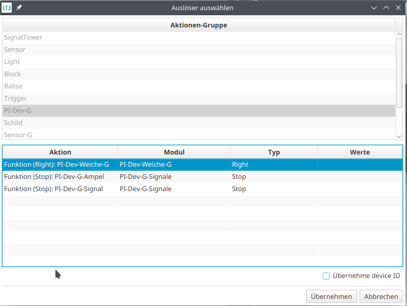
Select the turnout and then click “Apply.” When applying, suitable scripts were automatically created for all functions of the turnout:
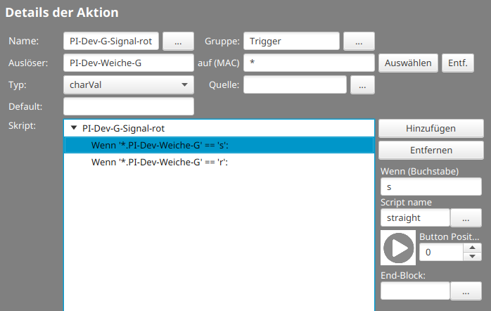
For the example, you now only need to call the command “Red” for the signal when the turnout state is “s” (straight). To do this, add the “call” command by marking the “s” condition and then clicking “Add”:
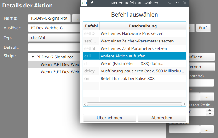
Select “call” and click “Apply.” Then select the action to the right of the script area (here PI-Dev-G-Signal) and then choose the parameter for the action (here “Hp0_Bar” for semaphore signal red):
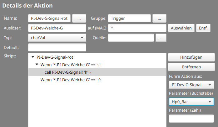
Finally, click “Upload” to save the changed config in the CTC module.
Note: Since the garden railway turnout in the example determines its position with sensors, the signal closure also works if the turnout is manually switched. See the article “LGB Turnout with Position Sensor”.
B.04. Config Example: Balise Dependent on Turnouts and Signal
In this example from our exhibition layout, there is a balise at the entrance of a station. If the turnouts are set so that entry to track 2 is possible, it should be linked to its signal.
In the track plan, the two involved turnouts, the signal, and the balise are labeled.
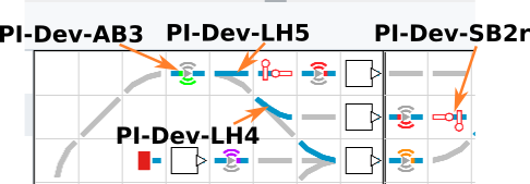
The balise should function as follows:
- Free passage (balise green) when the turnout “PI-Dev-LH5” is set to straight.
- Brake to minimum speed (balise orange) when the turnouts “PI-Dev-LH5” are set to right and “PI-Dev-LH4” to left, and the signal “PI-Dev-SB2r” shows red.
- Slow passage (balise yellow) in all other cases.
It should be clear that the balise needs three triggers, namely one for each of the turnouts “PI-Dev-LH4” and “PI-Dev-LH5”, as well as one for the signal. The triggers are appropriately named to include the name of the activator:
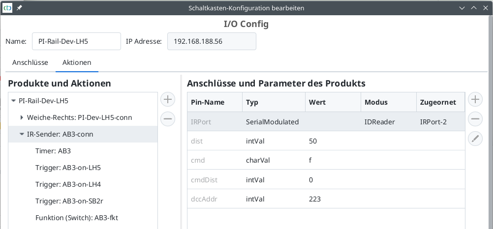
The triggers set the command (“cmd”) of the balise only in the cases where there is no dependency on the state of the other participants. For all other cases, a new function “AB3-fkt” has been added, which decides how the command should be set.
The trigger reacting to the turnout “PI-Dev-LH5” sets the command Free Passage (balise green) when straight (‘s’). When right (‘r’) it calls the function “AB3-fkt”:
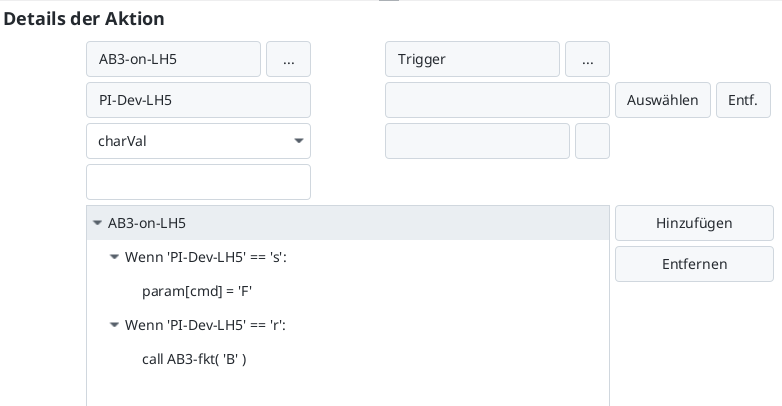
The trigger reacting to the turnout “PI-Dev-LH4” sets the command Slow Passage (balise yellow) when straight (‘s’). When left (‘l’) it calls the function “AB3-fkt”:
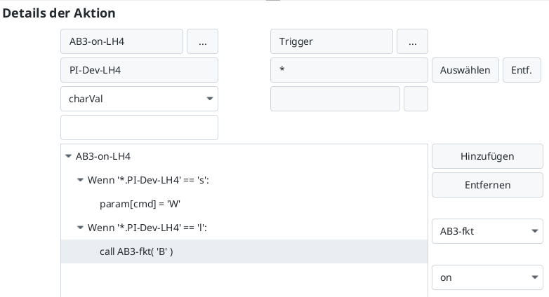
The trigger reacting to the signal “PI-Dev-SB2r” always calls the function “AB3-fkt”:
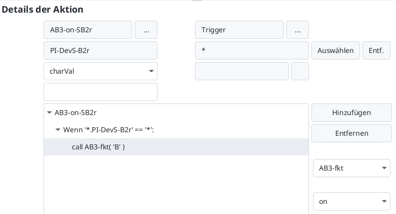
The real magic happens in the function “AB3-fkt”. It uses the trick that the state of a trigger is always the value of its activator.
So, if the turnout LH5 is switched to right (‘r’), the CTC-App calls the trigger “AB3-on-LH5” and assigns it the new value of the turnout (‘r’). The state (value) of the trigger is also set to ‘r’. This makes it possible for the function “AB3-fkt” to check the state of the turnouts “PI-Dev-LH4” and “PI-Dev-LH5” as well as the signal “PI-Dev-SB2r” and set the command of the balise accordingly:
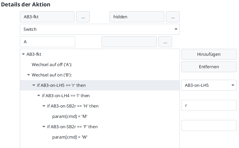
B.05. Configuration Example: Track with Signals for Both Directions
In this example from our exhibition layout, I show how to configure a track (block) with just two balises so that it works in both directions with signal coupling.
The basic idea is always the same: the information about the direction in which the track is currently being used must come from somewhere. In this case, I decided to turn off the unused light signal.
The track plan shows the two involved signals and the two balises labeled. It displays the state after the signal “B-Einfahrt-re” has been set to red:
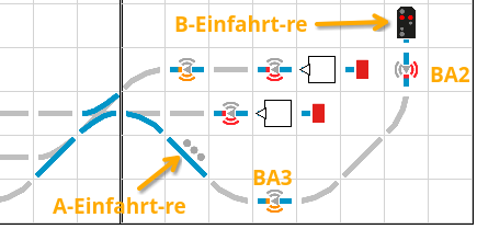
This is how the track plan looks after the signal “A-Einfahrt-re” has been set to red:
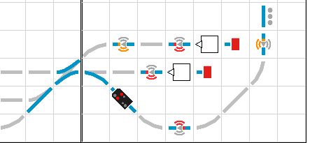
Each balise gets two triggers, one for each signal. Additionally, the signals receive a trigger that turns them off when the other signal is activated. The balises “BA2”, “BA3”, and signals “A-Einfahrt-re” and “B-Einfahrt-re” are distributed across three CTC modules and have a total of 6 triggers:
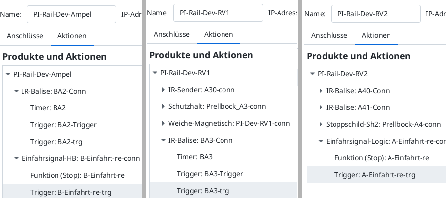
Compared to a normal balise trigger, the following changes:
- If the signal is in state “0” (off), nothing happens.
- In addition to the command (
cmd), the distance (cmdDist) is also set.
Here is the trigger on balise “BA2” listening to the signal “A-Einfahrt-re”:
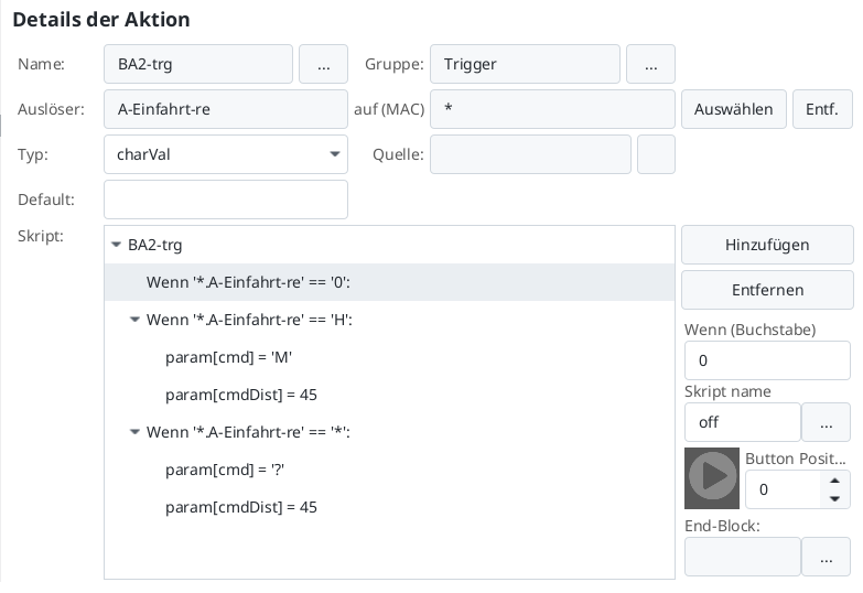
And the second trigger on balise “BA2” listening to the signal “B-Einfahrt-re”:
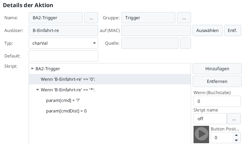
The triggers on the signals listen to the respective other signal and turn their signal off when the other one turns on. Here is the trigger on the signal “B-Einfahrt-re”:
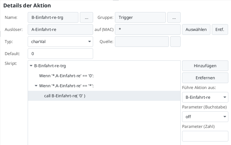
An important aspect of this approach is that both signals have an off state to prevent the triggers from endlessly activating each other in a loop.
For a semaphore signal, you would need to add an off state, even if it doesn’t physically exist. Since the balise is ineffective in the off state, the signal should then be open.